H U SQVARNA AUTOMOWE R ® 305 OPE R ATOR’S MAN UAL
TABLE OF CONTENTS 1. Introduction and safety .............................................................. 1.1 Introduction ..................................................................................... 1.2 Symbols on the product .............................................................. 1.3 Symbols in the Operator’s Manual ......................................... 1.4 Safety instructions ........................................................................ 5 5 6 7 8 2. Presentation .......
MEMO Serial number: PIN code: Dealer: Dealer’s telephone number: If the mower is unexpectedly stolen, it is important to notify your dealer of this. Provide the serial number of the mower so that is can be registered as stolen in the central systems at Husqvarna AB. It is an important step in theft protection procedure which reduces interest in the buying and selling of stolen mowers. www.automower.
1. INTRODUCTION AND SAFETY 1. Introduction and safety 1.1 Introduction Congratulations on your choice of an exceptionally high quality product. To get the best results from your Husqvarna Automower® requires knowledge of its function. This Operator's Manual contains important information about the mower, how it must be installed and how to use it. As a complement to this Operator's Manual, there is more information available on the Automower® website, www.automower.com.
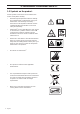
1. INTRODUCTION AND SAFETY 1.2 Symbols on the product These symbols can be found on the robotic lawn mower. Study them carefully. • Read through the Operator’s Manual carefully and understand the content before using your Automower®. The warnings and safety instructions in this Operator’s Manual must be carefully followed if the mower is to be used safely and efficiently. • Automower® can only start when the main switch is moved to the 1 position and the correct PIN code has been entered.
1. INTRODUCTION AND SAFETY 1.3 Symbols in the Operator’s Manual These symbols can be found in the Operator’s Manual. Study them carefully. • Turn the main switch to 0 before carrying out any inspections and/or maintenance. • Always wear protective gloves when working with the mower’s underframe. • Never use a high-pressure washer or even running water to clean Automower®. • A warning box indicates a risk of personal injury exist, especially when the stated instructions are not followed.
1. INTRODUCTION AND SAFETY 1.4 Safety instructions Use • This robotic lawn mower is designed to mow grass in open and level ground areas. It may only be used with the equipment recommended by the manufacturer. All other types of use are incorrect. The manufacturer’s instructions with regard to operation, maintenance and repair must be followed precisely.
1. INTRODUCTION AND SAFETY • Husqvarna AB does not guarantee full compatibility between Automower® and other types of wireless systems such as remote controls, radio transmitters, buried electric animal fencing or similar. Transport The original packaging should be used when transporting Automower® over long distances. To safely move from or within the working area: 1. Press the STOP button to stop the mower. If security is set to the medium or high level (see 6.
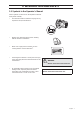
2. PRESENTATION 2. Presentation This chapter contains information that is important to be aware of when planning the installation. An installation of Husqvarna Automower® includes four main components: • The Automower® is a robotic lawn mower that mows the lawn by essentially operating in a random pattern. The mower is powered by a maintenance-free battery. • Charging station, where your Automower® returns when the charge level in the battery becomes too low.
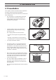
2. PRESENTATION 2.1 What’s what? 2 3 5 4 1 6 7 15 14 11 8 12 9 13 17 10 16 20 18 19 21 22 23 24 The numbers in the picture correspond to: 1. 2. 3. 4. 5. 6. 7. 8. 9. 10. 11. 12. 13.
2. PRESENTATION 2.2 Function Capacity Automower® is recommended for lawns up to 500 m2 in size. How big an area Automower® can keep cut depends primarily on the condition of the blades and the type, growth and moisture of the grass. The shape of the garden is also significant. If the garden mainly consists of open lawns, Automower® can mow more per hour than if the garden consists of several small lawns separated by trees, flower beds and passages.
2. PRESENTATION Working method The Automower® automatically mows the lawn. It continuously combines mowing and charging. The mower starts to search for the charging station when the battery charge becomes too low. Automower® does not mow when it is searching for the charging station. When Automower® searches for the charging station, it first searches irregularly for the guide wire. Then it follows the guide wire to the charging station, turns around just in front of the station and backs into it.
2. PRESENTATION The control panel on the top of Automower® is where you manage all the mower settings. Open the control panel cover by pressing down the STOP button. When the main switch is set to position 1 for the first time, a start-up sequence begins which includes: language selection, time format, date format and the four-digit PIN code and setting the time and date, see 3.8 First start-up and calibration on page 32.
3. INSTALLATION 3. Installation This chapter describes how you install the Husqvarna Automower®. Before starting the installation read the previous chapter 2. Presentation. Read also through this entire chapter before beginning the installation. How the installation is made also affects how well Automower® will work. It is therefore important to plan the installation carefully. Planning is simplified if you make a sketch of the working area, including all obstacles.
3. INSTALLATION • Transformer (20) • Low voltage cable (17) • Staples (21) • Connector for the loop wire (18) • Screws for the charging station (19) • Measurement gauge (22) • Solderless coupler for the loop wire (23) During installation you will also need: • Hammer/plastic mallet to simplify putting the staples in the ground • Combination pliers for cutting the boundary wire and pressing the contact units together. • Edge cutter/straight spade if the boundary wire must be buried.
3. INSTALLATION The charging station must be positioned with a great deal of free area in front of it (at least 3 metres). It should also be centrally placed in the working area so that Automower® finds it easier to reach all areas in the working area. Do not put the charging station in confined spaces in the working area. There must be a straight boundary wire, at least 1.5 metres long, to the right and left of the charging station.
3. INSTALLATION If the installation is done in a working area with a steep slope (such as around a house on a hill), the charging station should be placed in the area at the bottom of the slope. This makes it easier for the lawn mower to follow the guide wire to the charging station. The charging station should not be placed on an island as this limits the laying of the guide wire in an optimal way.
3. INSTALLATION The transformer shall be mounted on a vertical surface, for example a house wall. Mount the transformer with screws in the two attachment points. Securing screws are not included. Choose screws suitable for the wall material. Mount the transformer at a height such that there is no risk the transformer can become submerged in water (minimum 30 cm from the ground). The transformer must never be placed on the ground.
3. INSTALLATION IMPORTANT INFORMATION The transformer may not be exposed to direct sunlight. 3.3 Charging the battery As soon as the charging station is connected, it is possible to charge the mower. Set the main switch to the 1 position. Place Automower® in the charging station to charge the battery while the boundary and guide wires are being laid. If the battery is flat, it takes around 80 to 100 minutes to fully charge it.
3. INSTALLATION 3.4 Installation of the boundary wire The boundary wire can be installed in one of the following ways: 1. Securing the wire to the ground with staples. It is preferable to staple down the boundary wire if you want to make adjustments to the boundary wire during the first few weeks of operation. After a few weeks the grass will have grown over the wire making it no longer visible. Use a hammer/plastic mallet and the staples supplied when carrying out the installation. 2. Bury the wire.
3. INSTALLATION Boundaries for the working area If a high obstacle, for example a wall or fence, borders the working area, the boundary wire should be laid 30 cm from the obstacle. This will prevent Automower® from colliding with the obstacle and reduce body wear. About 20 cm around the fixed obstacle will not be mown. If the working area borders against a small ditch, for example, a flower bed or a small elevation, e.g.
3. INSTALLATION Boundaries within the working area Use the boundary wire to demarcate areas inside the working area by creating islands around obstacles that can not withstand a collision, for example, flower beds and fountains. Run the cable out to the area, route it around the area to be demarcated and then back along the same route. If staples are used, the wire should be laid under the same staple on the return route.
3. INSTALLATION Passages when mowing Long and narrow passages and areas narrower than 1.5 - 2 metres should be avoided.When the Automower® mows there is a risk that it travels around in the passage or area for a period of time. The lawn will then look flattened. Slopes The boundary wire can be laid across a slope that slants less than 10 %. The boundary wire should not be laid across a slope that is steeper than 10 %. There is a risk of Automower® finding it difficult to turn there.
3. INSTALLATION Laying out the boundary wire If you intend to staple down the boundary wire: • Cut the grass very low with a standard robotic lawn mower or a trimmer where the wire is to be laid. It will then be easier to lay the wire close to the ground and the risk of the mower cutting the wire or damaging the insulation of the wire is reduced. • Make sure to lay the boundary wire tight to the ground and secure the staples close together with approximately 75 cm between each staple.
3. INSTALLATION Laying the boundary wire in towards the charging station The boundary wire must be laid in line with the rear end of the charging station. If the boundary wire is laid in any other way, the robotic lawn mower may find it hard to find the charging station. In many cases, the straight wire section to the left of the charging station can be reduced to 1 metre.
3. INSTALLATION 3.5 Connecting the boundary wire Connect the boundary wire to the charging station: IMPORTANT INFORMATION The boundary wire must not be crossed when connecting to the charging station. The right hand wire end must be connected to the right hand pin on the charging station and the left hand wire end to the left pin 1. Place the cable ends in the connector: • Open the connector. • Place the wire in the connector grip. 2. Press the connector together using a pair of pliers.
3. INSTALLATION 3.6 Installation of the guide wire The guide wire is a wire that is laid away from the charging station, for instance out towards a remote part of the working area or through a narrow passage and then connected with the boundary wire. The guide wire is used by the mower to find its way back to the charging station but also to guide the mower to remote areas of the garden.
3. INSTALLATION Placement and connection of the guide wire 1. Draw the wire through the slot in the bottom of the charger plate. 2. Fit the connector to the guide wire in the same way as for the boundary wire in 3.5 Connecting the boundary wire. Connect it to the contact pin on the charging station that is labelled “guide”. 3. Route the guide wire at least 2 metres straight out from the front edge of the charging plate.
3. INSTALLATION • - In the passage, the guide wire must therefore be placed so that the mower has as much space to run in as possible. The distance between the boundary wire and the guide wire must however be at least 30 cm. Maximum distance At least 30 cm At least 2 m If the guide wire has to be installed on a steep slope, it is an advantage to lay the wire at an angle to the slope. This makes it easier for the mower to follow the guide wire on the slope. Avoid laying the wire at sharp angles.
3. INSTALLATION 6. Connect the guide wire to the boundary wire with the help of a solderless coupler: Insert the boundary wire in each of the holes in the coupler. Insert the guide wire in the centre hole in the coupler. Check that the wires are fully inserted into the coupler so that the ends are visible through the transparent area on the other side of the coupler. Use pliers to completely compress the button on the coupler. It does not matter which holes are used to connect each wire. 7.
3. INSTALLATION 3.8 First start-up and calibration Before the mower is operated, a start-up sequence in the mower's menu must be carried out as well as an automatic calibration of the guide signal. The calibration is also a good test to see that the installation of the guide wire has been done in such a way that the mower can easily follow the guide wire from the charging station. 1. Set the main switch to the 1 position. 2. Open the control panel cover by pressing the STOP button.
3. INSTALLATION 3.9 Test docking with the charging station Before using the mower, check that it can follow the guide wire all the way to the charging station and easily docks with the charging station. Perform the test below. 1. Open the control panel cover by pressing the STOP button. 2. Place the mower close to the point where the guide wire is connected to the boundary wire. Place the mower about 2 metres from the guide wire, facing the guide wire. 3.
4. USE 4. Use 4.1 Charging a discharged battery When Husqvarna Automower® is new or has been stored for a long period the battery will not be charged and needs to be charged before starting. Charging takes approximately 80 to 100 minutes. 1. Set the main switch to the 1 position. 2. Place Automower® in the charging station. Open the cover and slide the mower in as far as possible to ensure proper contact between the mower and the charging station. 3.
4. USE 4.2 Using the timer The lawn should not be cut too often to obtain the best mowing result. Use the timer function (see 6.3 Timer (1) on page 43) to avoid a downtrodden lawn and to get the maximum life from your Automower®. When setting the timer, calculate that Automower® mows around 30 m2 per hour and day. For example; if the working area is 300 m2, the mower must operate for 10 hours a day. The factory setting for the timer is 07:00-23:00 and it can operate every day of the week.
4. USE 4.3 Starting 1. Set the main switch to the 1 position. 2. Press the STOP button to open the control panel cover. 3. Enter the PIN code. The PIN code request can be disabled. For more information about theft protection, see 6.5 Security (3). 4. Push the Start button. 5. Shut the cover within 10 seconds. If the mower is parked in the charging station, it will only leave the charging station when the battery is fully charged and if the timer is set to allow the mower to operate.
4. USE 4.6 Adjusting the cutting height The cutting height can be varied from MIN (2 cm) to MAX (5 cm). During the first week after a new installation, the cutting height must be set to MAX to avoid damaging the loop wire. After this, the cutting height can be lowered one step every week until the desired cutting height has been reached. 1 2 3 4 5 If the grass is long it is appropriate to let Automower® start mowing at the MAX cutting height.
5. CONTROL PANEL 5. Control panel All forms of commands and settings for Husqvarna Automower® are made via the control panel. All functions are accessed via a number of menus. The control panel consists of a display and a keypad. All information is shown on the display and all input is done using the buttons. When the stop button has been pressed and the cover is opened, the operation window appears to display the clock, selected operating mode, number of mowing hours, battery status and timer setting.
5. CONTROL PANEL 5.1 Operation selection The operation selection button is symbolised by a house. When the button has been pressed, the selected operation mode is shown in the display. By consecutively pressing the button many times, one can choose between three different operation modes. 1. HOME: Sends the mower to the charging station. It remains here until another operation mode is selected. The text Home is shown in the operation window.
5. CONTROL PANEL 5.3 Numbers The number keys are used for instance to enter the PIN code or time settings. The number keys can also be used to enter a number series for shortcuts to the various menus. For more information on number series, see 6.1 Main menu on page 41. 5.4 Main switch Set the main switch in the 1 position to start Automower®. Set the main switch in the 0 position when the mower is not in use or work is being carried out on the blade disc.
6. MENU FUNCTIONS 6. Menu functions 6.1 Main menu The main menu consists of four options: • Timer (1) • Installation (2) • Security (3) • Settings (4) There are a number of submenus under each option. You can access all the functions to set Automower® settings via these. Browse between menus Browse the main menu and submenus using the multi-choice buttons. Enter values and times using the number keys and confirm each selection with the multi-choice button marked OK.
Work period 1 42 - English Work period 2 Guide width Medium Proportion Often Test out Always Distance Test in Test settings Installation Remote start Medium Wide Rarely Reset timer Narrow Never Work days Timer Drive past wire Low Change PIN code New loop signal Medium High Security level Security Set time Set date Time & Date Time format Language Settings Date format Return to customer settings 6. MENU FUNCTIONS 6.
6. MENU FUNCTIONS 6.3 Timer (1) The lawn should not be cut too often to obtain the best mowing result. Consequently, it is important to limit the operating time using the timer function if the working area is less than the mower's working capacity. When Automower® is allowed to mow too much, the lawn may appear flattened. Besides, the mower is subjected to unnecessary wear.
6. MENU FUNCTIONS 6.4 Installation (2) The following operating settings are available via this selection in the main menu. • • Guide width (2-1) to select the distance from the guide wire the mower is allowed to travel when it follows this to and from the charging station. Remote start (2-2) to control the mower so that it can easier reach remote parts of the garden. • Test settings (2-3) to check the above settings.
6. MENU FUNCTIONS Narrow (2-1-3) With a narrow corridor, Automower® runs straight over the guide wire. The Narrow corridor setting is not normally recommended, but in a garden with one or many narrow passages, a narrow corridor may be the only option. The Narrow corridor setting increases the risk for tracks forming along the guide wire. IMPORTANT INFORMATION The distance the mower maintains from the guide wire varies depending on the layout of the working area.
6. MENU FUNCTIONS • Distance (2-2-2) Enter the distance in metres from the charging station along the guide wire to the remote area where the mower begins mowing. Tip! Use the Test OUT (2-3-2) function to determine how far it is to the remote area. The distance, stated in metres, will be shown in the mower display. Test settings (2-3) In the Test settings menu, it is possible to test settings for Remote start (2-2) and that the selected guide width works for the garden in question.
6. MENU FUNCTIONS State a distance that easily exceeds the true distance. The maximum distance that can be stated is 500 metres. Place Automower® in the charging station and select Test OUT (2-3-2). The mower will immediately leave the charging station. The distance will be shown on the display, stated in metres, as the mower runs. Stop the mower at the required position and note the distance. Enter the number of metres shown in Distance for the area in question.
6. MENU FUNCTIONS IMPORTANT INFORMATION We recommend using the High security level at all times. Time lock This function entails that Automower® cannot be started after 30 days without first entering the correct PIN code. When the 30 days has passed Automower® will continue to mow as normal, but the Enter PIN code message appears when the cover is opened. Enter your code again and press OK.
6. MENU FUNCTIONS 6.6 Settings (4) The following operating settings are available via this selection in the main menu. • • • Time & Date (4-1) to set the current time and date, and the required time and date format. Language (4-2) to select which language is to be used in the menus. Timer Installation Time & Date Security Language Settings Reset customer setting Reset customer settings (4-3) to reset the mower to the settings it had when it left the factory.
7. GARDEN EXAMPLE 7. Garden example - Proposed installation and settings The mower's behaviour is controlled to a certain extent by what settings are made. Adapting the mower’s garden settings according to the shape of the garden makes it easier for the mower to frequently reach all parts of the garden and in doing so achieve a perfect mowing result. Different gardens require different settings. The following pages outline a number of examples of gardens with installation and setting proposals.
7. GARDEN EXAMPLE Proposals for installation and settings Area 500m2. Open area. Timer 07:00-23:00 (factory setting) Monday-Sunday Proportion Never Guide width Wide Remarks Open area without difficult obstacles. Area 500m2. A number of islands and a 25% slope. Timer 07:00-23:00 (factory setting) Monday-Sunday Proportion Rarely (factory setting) Guide width Medium Remarks Place the charging station in the lower part of the working area. Lay the guide wire at an angle over the steep slope.
7. GARDEN EXAMPLE Proposals for installation and settings Area 250m2. U-shaped garden linked with a narrow passage. Timer 07:00 - 23:00 Monday - Friday Proportion Medium Guide width Medium 1.5 m Remarks The guide wire must be placed along the narrow passage to ensure the mower can with ease locate the charging station from the left hand side of the working area. As the left hand area is nearly half of the total area, select Proportion: Medium. Area 150m2.
8. MAINTENANCE 8. Maintenance Check and clean Husqvarna Automower® regularly and replace worn parts if necessary to improve operating reliability and to ensure a longer service life. See 8.4 Cleaning on page 55. When Automower® is first used, the blade disc and blades should be inspected once a week. If the amount of wear during this period has been low, the inspection interval can be increased. It is important that the blade disc rotates easily. The edges of the blades should not be damaged.
8. MAINTENANCE 8.1 Winter storage Automower® Automower® must be cleaned carefully before putting it away for the winter, see 8.4 Cleaning on page 55. Charge the battery fully before winter storage. Then set the main switch to 0. Inspection of wear components such as mower blades and bearings in the rear wheel. Rectify if necessary to make sure the mower is in good condition prior to next season. Store the mower upright in a dry area free from frost, preferably in the mower's original packaging.
8. MAINTENANCE 8.4 Cleaning It is important to keep Automower® clean. A mower with large amounts of grass stuck to it will not cope as well with slopes. It is recommended to clean using a brush and a spray with water IMPORTANT INFORMATION Never use a high-pressure washer or even running water to clean Automower®. Solvent must never be used when cleaning. Underframe and blade disc 1. Set the main switch to the 0 position. 2. Wear protective gloves. 3. Lift Automower® onto its side. 4.
8. MAINTENANCE Body Use a damp, soft sponge or cloth to clean the body. If the body is very dirty it may be necessary to use a soap solution or washing-up liquid. Charging station Clean the charging station regularly from grass, leaves, twigs and other objects that may impede docking. 8.5 Transport and removal Secure the machine during transport. It is important that Automower® does not move when it is being transported, for instance, between lawns. 8.
8. MAINTENANCE 4. Remove the screw. Use a straight slot or cross-tip screwdriver. 5. Remove the blade and the screw. 6. Screw on the new blade and the new screw. 8.8 Battery The battery is maintenance-free, but has a limited life span of 2-4 years. Battery life is dependent on the length of the season and how many hours per day the Automower® is used. A long season or many hours of use per day means that the battery must be replaced more regularly.
8. MAINTENANCE 5. Pull out the battery by pulling on the strap. 6. Set the main switch to position 0. 7. Turn the mower upside down. 8. Fit a new Husqvarna original battery. NOTE! Press on the contact strip to fit the battery in place 9. Fit the battery cover. The sealing strip is reusable and does not have to be replaced. 10. Screw in place the four screws for the battery cover (Torx 20).
9. TROUBLE SHOOTING 9. Trouble shooting In this chapter, we have listed a number of messages which may be shown in the display if there is a malfunction. There is a proposal as to the cause and steps to take for each message. This chapter also presents some symptoms that can guide you if the mower does not work as expected. More suggestions for steps to take in the event of malfunction or symptoms can be found on www.automower.com. 9.
9. TROUBLE SHOOTING Message Cause Action Trapped Automower® has got caught in something. Free Automower® and rectify the reason for it getting trapped. Automower® gets stuck behind a number of obstacles. Check if there are any obstacles which make it hard for Automower® to move on from this place. The boundary wire connections to the charging station are crossed. Check that the boundary wire is connected correctly. The boundary wire is too close to the edge of the working area.
9. TROUBLE SHOOTING Message Cause Action No drive Automower® has got caught in something. Free the mower and rectify the reason for the lack of drive. If it is due to wet grass, wait until the lawn has dried before using the mower. The working area includes a steep slope. Maximum guaranteed slope is 25%. Steeper slopes should be isolated. See 3.4 Installation of the boundary wire on page 21. The guide wire is not laid at an angle on a slope.
9. TROUBLE SHOOTING 9.2 Indicator lamp in the charging station For a fully functional installation, the indicator lamp in the charging station must emit a solid green light. If something else appears, follow the troubleshooting guide below. There is more troubleshooting help on www.automower.com. If you still need help with troubleshooting, please contact the local dealer.
9. TROUBLE SHOOTING 9.3 Symptom If your Automower® does not work as expected, follow the troubleshooting guide below. There is a FAQ (Frequently Asked Questions) on www.automower.com which provides more detailed answers to a number of standard questions. It you still cannot find the reason for the fault, contact the local dealer.
9. TROUBLE SHOOTING Symptom Cause Action Automower® vibrerar Damaged blades lead to imbalance in the cutting system. Inspect the blades and screws and replace them if necessary. See 8.7 Blades on page 56. Many blades in the same position lead to imbalance in the cutting system. Check that only one blade is fitted at each screw. Automower® moves but the blade disc does not rotate Automower® is looking for the charging station. No action.
9. TROUBLE SHOOTING 9.4 Finding breaks in the loop wire Breaks in the loop wire are usually the result of unconscious physical damage to the cable such as when gardening with a shovel. In countries with ground frost, even sharp stones that move in the ground can damage the wire. Breaks can also be due to high tension in the wire during installation. Mowing the grass too low right after the installation can damage cable insulation.
9. TROUBLE SHOOTING 3. Connect the charging station to the power supply. Switch the connections between the guide wire and the boundary wire in the charging station. a) Switch connection A1 and Guide. If the indicator lamp flashes yellow, then the break is somewhere on the boundary wire between A1 and the point where the guide wire is connected to the boundary wire (thick black line in the illustration). Guide b) Put A1 and Guide back in their original positions. Then switch A2 and Guide.
9. TROUBLE SHOOTING 4. a) Assume that the indicator lamp blinked yellow in test a) above. Reset all connections to their original positions. Then disconnect A2. Connect a new loop wire to A2.Connect the other end of this new loop wire somewhere at the centre of the installation. If the indicator lamp is green or flashing yellow, then the break is somewhere in the wire between the disconnected end to the point where the new wire is connected (thick black line in the illustration below).
9. TROUBLE SHOOTING 5. When the break is found, the damaged section must be replaced with a new wire. The damaged section can be cut out if it is possible to shorten the boundary wire. Always use original couplers.
10. TECHNICAL DATA 10. Technical data Data Automower® 305 Dimensions Length 55 cm Width 39 cm Height 25 cm Weight 7 kg Electrical system Battery Specialised Lithium-Ion battery, 18 V/1.
12. EU DECLARATION OF CONFORMITY 12. EU declaration of conformity EU Declaration of Conformity (only applies to Europe) Husqvarna AB, SE-561 82 Huskvarna, Sweden, hereby declares that robotic lawnmower Husqvarna Automower® 305 from 2012's serial numbers and onwards (the year is clearly stated in plain text on the rating plate with subsequent serial number), complies with the requirements of the COUNCIL'S DIRECTIVE: • Directive “relating to machinery” 2006/42/EC.
ORIGINAL INSTRUCTIONS AUTOMOWER® is a trademark owned by Husqvarna AB. Copyright © 2012 HUSQVARNA. All rights reserved.