manual GB Operator’s Please read the operator’s manual carefully and make sure you understand the instructions before using the machine. de ES Manual instrucciones Lea detenidamente el manual de instrucciones y asegúrese de entender su contenido antes de utilizar la máquina. DE Bedienungsanweisung Lesen Sie die Bedienungsanweisung sorgfältig durch und machen Sie sich mit dem Inhalt vertraut, bevor Sie das DC 5500 Gerät benutzen.
Contents 2 - English
Contents English Contents Key to symbols 4 Safety Instructions 5 Introduction 6 Transportation 6 Storage 6 What is what 7 Operation (dry use) 11 Operation (wet use) 12 Troubleshooting 13 Maintenance 14 Technical data 15 English - 3
Key to symbols Key to symbols The symbols below are used on the machine and in this Operator’s Manual. It is important that the user understands the significance of these in order to work with the machine safely. Please read the operator’s manual carefully and make sure you understand the instructions before using the machine. Inspection and/or maintenance should be carried out with the motor switched off and the plug disconnected. Visual check.
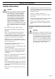
Safety Instructions Safety Instructions • Check that the cord and extension cord are intact and in good condition. Never use the machine if the cord is damaged, hand it in to an authorized service workshop for repair. • Do not use a rolled up extension cord • The machine should be connected to an earthed outlet socket. • Check that the mains voltage corresponds with that stated on the rating plate on the machine.
Introduction Introduction The Husqvarna DC 5500 dust extraction/vacuum unit is designed for wet or dry suction of concrete dust and liquid slurry. This manual covers the Husqvarna DC 5500 dust collector/ vacuum unit. It is extremely important all users be familiar with the contents of this manual before commencing operation of either machine. Failure to do so may result in damage to machinery or expose operator to unnecessary dangers.
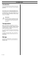
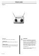
What is what 2. 10. 3. 9. 4. 11. 13. 1. 12. 5. 6. 8. 7. 14. What is what 1. Small toggle latch 8. Frame 2. Filter link hose 9. Small toggle latch 3. Large toggle latch 10. Primary filter housing 4. Secondary filter housing 11. Hose attachment fitting 5. Control box 12. Collection cone 6. Vacuum pump 13. Accessory power point 7. Rear wheel 14.
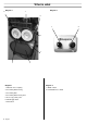
What is what Diagram 1 2. Diagram 2 1. 5. 1. 6. 7. 3. 4. Diagram 1 Diagram 2 1. Filter link hose coupling 1. Off/On switch 2. Secondary filter housing 2. Forward/Reverse switch 3. Secondary filter 4. Secondary filter housing door 5. Accessory power point 6. Small toggle latch 7. Control box 8 - English 2.
What is what Diagram 3 2. 1. 3. 4. Diagram 3 1. Primary clamp part 2. Primary filter sock part 3. Primary filter seal. Outer part (kit) 4. Primary filter seal.
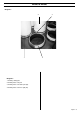
What is what Diagram 4. 1. Control box The control system consists of two switches: 1. On/Off swich. Turns machine off in OFF position and on in ON position. 2. Fwd/Rev switch. Changes direction of vacuum pump. Sometimes direction of vacuum will need to be reversed depending on phase order of power supply. 2. IMPORTANT! Direction should NEVER be changed while machine is switched to ON position (this is why there is a lock on the FWD/REV switch).
Operation (dry use) Operation (dry use) Setting up 1. Switch the machine to the off position. 2. Using a large rubber hammer/mallet, tap the top surface of the primary filter housing 10 times. While this is happening you will notice all the dust from inside the unit drop into the plastic bag attached to the collection cone. 1. Position the vacuum in the working area. Changing the dust bags. 2. Ensure dust collection bag is fitted to collection cone. 3.
Operation (wet use) Operation (wet use) The Husqvarna DC 5500 can also be used for collection of wet materials such as slurry formed from the wet grinding process. In order to use the machine for wet collection, simply remove the primary filter socks from the unit. 1. Disconnect the filter link hose. 2. Release the large toggle latch. 3. Fold the primary filter housing into the forward position. 4. Release the 2 small toggle latches. 5. Lift the primary filters from within the primary filter housing.
Troubleshooting Troubleshooting Whilst every measure has been undertaken by the manufacturer to ensure smooth reliable operation of the machine, sometimes problems can arise. The following possible problems may arise: 1. The machine will not run. Ensure power connected to machine is on. If ma chine still will not run, remove cover from control box and test for presence of power supply at top of left side contactor. If no power at contactors, test power supply at power source.
Maintenance Maintenance The following maintenance steps should be followed to maximise optimal performance and reliability of the machine: Daily Inspection of Micro Filters: It is highly recommended that operators check dust levels inside secondary filter housing on a daily basis. This will indicate the effectiveness of the primary filters. If there is dust building up inside the secondary filter housing, it is more than likely due to one of the following reasons: 1.
Technical data Technical data Noise emissions (see note 1) Sound power level, measured dB(A) 92 Sound power level, guaranteed LWA dB(A) 93 Sound levels (see note 2) Sound pressure level at the operators ear, dB(A) 77 Note 1: Noise emissions in the environment measured as sound power (LWA) in conformity with EN 60335-2-69. Note 2: Noise pressure level according to EN 60335-2-69. Reported data for noise pressure level has a typical statistical dispersion (standard deviation) of 1.0 dB(A).
Índice 16 - Spanish
Índice Español Índice Significado de los símbolos 18 Instrucciones de seguridad 19 Introducción 20 Transporte 20 Almacenamiento 20 Componentes de la máquina 21 Manejo (uso en seco) 25 Manejo (uso mojado) 26 Localización de averías 27 Mantenimiento 28 Datos técnicos 29 Spanish - 17
Significado de los símbolos Significado de los símbolos Los siguientes símbolos se usan en la máquina y en este manual de instrucciones. Es importante que el usuario entienda el significado de los mismos para trabajar con la máquina de forma segura. Antes de utilizar la máquina, lea atentamente el manual de instrucciones y asegúrese de haber comprendido las instrucciones. La inspección y/o el mantenimiento se deberá llevar a cabo con el motor apagado y el enchufe desconectado. Comprobación visual.
Instrucciones de seguridad Instrucciones de seguridad ADVERTENCIA La máquina no se podrá poner en marcha bajo ninguna circunstancia si no se observan las instrucciones de seguridad. Si el usuario no cumpliera este requisito, Husqvarna Construction Products Sweden AB o sus representantes no tendrán ningún tipo de responsabilidad, ya sea directa o indirecta. Léase detenidamente estas instrucciones de manejo y asegúrese de que entiende su contenido antes de empezar a usar la máquina.
Introducción Introducción La unidad aspiradora/extractora de polvo Husqvarna DC 5500 se ha diseñado para la succión en mojado o en seco del polvo de cemento y lechada de cemento. Este manual se refiere a la unidad aspiradora/extradora de polvo Husqvarna DC 5500. Es extremadamente importante que todos los usuarios estén familiarizados con el contenido de este manual antes de empezar a manejar una de las máquinas.
Componentes de la máquina 2. 10. 3. 9. 4. 11. 13. 1. 12. 5. 6. 8. 7. 14. Componentes de la máquina 1. Cerrojo de palanca pequeño 8. Bastidor 2. Manguera de enlace al filtro 9. Cerrojo de palanca pequeño 3. Cerrojo de palanca grande 10. Caja del filtro principal 4. Caja del filtro secundario 11. Accesorio de acoplamiento de manguera 5. Caja de control 12. Cono de recogida 6. Bomba de vacío 13. Punto accesorio de toma de corriente 7. Rueda trasera 14.
Componentes de la máquina Diagrama 1 2. Diagrama 2 1. 5. 1. 6. 7. 3. 4. Diagrama 1 Diagrama 2 1. Acoplamiento de la manguera de enlace al filtro 1. Interruptor Off/On 2. Caja del filtro secundario 2. Interruptor adelante/atrás 3. Filtro secundario 4. Puerta de la caja del filtro secundario 5. Punto accesorio de toma de corriente 6. Cerrojo de palanca pequeño 7. Caja de control 22 - Spanish 2.
Componentes de la máquina Diagrama 3 2. 1. 3. 4. Diagrama 3 1. Abrazadera principal 2. Plantilla del filtro principal 3. Junta del filtro principal. Parte exterior (kit) 4. Junta del filtro principal.
Componentes de la máquina Diagrama 4 1. Caja de control El sistema de control consta de dos interruptores: 1. Interruptor On/Off. Apaga la máquina en posición OFF y la enciende en posición ON. 2. Interruptor Fwd/Rev. Cambia la dirección de la bomba de vacío. A veces se deberá invertir la dirección de vacío dependiendo del orden de fases y la alimentación de corriente. 2.
Manejo (uso en seco) Manejo (uso en seco) 1. Apague la máquina en la posición off. 2. Usando un martillo / mazo de goma, dé 10 golpecitos a la parte superior de la superficie de la caja del filtro principal. Cuando esté haciendo esto, notará que todo el polvo del interior de la unidad caerá a la bolsa de plástico sujeta al cono de recogida. Puesta en marcha 1. Coloque la aspiradora en la zona de trabajo. 2. Asegúrese de que la bolsa de plástico se ha fijado al cono de recogida. 3.
Manejo (uso mojado) Manejo (uso mojado) La Husqvarna DC 5500 también se puede usar para recoger materiales líquidos como puede ser el lodo formado del proceso de desbastado en mojado. Para usar la máquina para recogida en mojado, basta con que quite las plantillas del filtro primario de la unidad. 1. Desacople la manguera de enlace al filtro. 2. Suelte el cerrojo de palanca grande. 3. Pliegue la caja del filtro principal hacia delante. 4. Suelte los 2 cerrojos de palanca pequeña. 5.
Localización de averías Localización de averías Aunque el fabricante ha llevado a cabo todas las medidas posibles para garantizar un funcionamiento fiable de la máquina, a veces pueden surgir problemas. Pueden surgir los siguientes problemas: 1. La máquina no funciona. Asegúrese de que la máquina está conectada a la corriente y está encendida.
Mantenimiento Mantenimiento Para maximizar el rendimiento óptimo y la fiabilidad de la máquina se deberán realizar las siguientes labores de mantenimiento: Inspección diaria de los microfiltros: Se recomienda encarecidamente que los operadores comprueben diariamente los niveles de polvo dentro de la caja del filtro secundario. Esto indicará la eficacia de los filtros primarios.
Datos técnicos Datos técnicos Emisiones de ruido (vea la nota 1) Nivel de potencia acústica medido dB(A) 92 Nivel de potencia acústica garantizado LWA dB(A) 93 Niveles acústicos (vea la nota 2) Nivel de presión acústica en el oído del usuario, dB(A) 77 Nota 1: Emisiones sonoras en el entorno medidas como potencia sonora (LWA) según la norma EN 60335-2-69. Nota 2: Nivel de presión sonora conforme a EN 60335-2-69.
Inhalt 30 - German
Inhalt Deutsch Inhalt Symbole 32 Sicherheitsanweisungen 33 Einleitung 34 Transport 34 Lagerung 34 Maschinenteile 35 Trockenschleifen 39 Nassschleifen 40 Störungsbehebung 41 Wartung 42 Technische Daten 43 German - 31
Symbole Symbole In diesem Bedienungshandbuch werden die nachstehend beschriebenen Symbole verwendet. Ein sicherer Betrieb der Maschine ist nur gewährleistet, wenn der Anwender die Bedeutung dieser Symbole kennt. Vor der Inbetriebnahme die Bedienungsanleitung aufmerksam durchlesen! Inspektions- und Wartungsarbeiten sind bei ausgeschaltetem Motor und gezogenem Netzstecker durchzuführen. ACHTUNG! Bei Schleifarbeiten entsteht Schleifstaub. Das Einatmen des Staubs gefährdet die Gesundheit.
Sicherheitsanweisungen Sicherheitsanweisungen • Zustand des Netz- und Verlängerungskabels vor Anschluss überprüfen. Kein Betrieb der Maschine bei beschädigtem Netzkabel. Die Maschine muss durch eine Fachwerkstätte repariert werden. • Bei Verwendung von Verlängerungskabel darf das Kabel nicht aufgerollt sein. • Die Maschine sollte nach Möglichkeit an eine Schukosteckdose angeschlossen werden. • Die Netzspannung muss der auf dem Typenschild der Maschine angegebenen Betriebsspannung entsprechen.
Einleitung Einleitung Die Staubsauganlage Husqvarna DC 5500 ist für Nassund Trockenschleifarbeiten geeignet und kann u.a. Betonstaub und Zementschlämme aufnehmen. In diesem Handbuch wird die Staubsauganlage Husqvarna DC 5500 beschrieben. Vor der Inbetriebnahme der Maschine ist das Handbuch vollständig durchzulesen. Bei Nichtbeachtung der Hinweise besteht die Gefahr von Maschinenschäden und Verletzungen.
Maschinenteile 2. 10. 3. 9. 4. 11. 13. 1. 12. 5. 6. 8. 7. 14. Maschinenteile 1. Kleiner Schnappriegel 8. Rahmen 2. Filteranschlussschlauch 9. Kleiner Schnappriegel 3. Großer Schnappriegel 10. Primärfiltertopf 4. Sekundärfiltertopf 11. Schlauchanschlussfitting 5. Steuerkasten 12. Sammeltrichter 6. Vakuumpumpe 13. Stromanschluss für Zubehör 7. Hinterrad 14.
Maschinenteile Abbildung 1 2. Abbildung 2 1. 5. 1. 6. 7. 3. 4. Abbildung 1 Abbildung 2 1. Filter, Schlauchanschluss 1. Aus/Ein-Schalter. 2. Sekundärfiltertopf 2. Vorwärts/Rückwärts-Drehrichtungsschalter. 3. Sekundärfilter 4. Sekundärfiltertopfklappe 5. Stromanschluss für Zubehör 6. Kleiner Schnappriegel 7. Steuerkasten 36 -German 2.
Maschinenteile Abbildung 3 2. 1. 3. 4. Abbildung 3 1. Primär, Klemmenteil 2. Primärfilter, Schlauchteil 3. Primärfilterdichtung. Außenteil (Satz) 4. Primärfilterdichtung.
Maschinenteile Abbildung 4 1. 2. WICHTIG! Steuerkasten Die Steuerung besteht aus zwei Schaltern: 1. Ein-/Ausschalter. Schaltet die Maschine ein (ON) und aus (OFF). 2. Fwd/Rev-Schalter. Ändert die Drehrichtung der Vakuumpumpe. Gelegentlich muss die Drehrichtung der Vakuumpumpe aufgrund der Phasenfolge der Stromversorgung umgekehrt werden. Die Drehrichtung darf auf keinen Fall bei eingeschalteter Maschine (Position ON) geändert werden (aus diesem Grund ist der FWD/REV-Schalter absperrbar).
Trockenschleifen Trockenschleifen Einrichtung 1. Gerät im Arbeitsbereich aufstellen. 1. Maschine ausschalten. 2. Mit einem großen Gummihammer / -klopfer 10 Mal auf die Oberfläche des Primärfiltertopfes schlagen. Dadurch fällt der gesamte, im Inneren der Einheit angesammelte Staub in den Kunststoffbeutel, der am Sammeltrichter befestigt ist. Auswechseln des Staubbeutels 2. Verbindung zwischen Kunststoffbeutel und Sammeltrichter kontrollieren. 3. Gerät an Stromversorgung anschließen und einschalten.
Nassschleifen Nassschleifen Die Husqvarna DC 5500 ist zum Aufsaugen der beim Nassschleifen anfallenden Schlämme geeignet. Dazu muss lediglich der Primärfilterschlauch aus der Maschine entfernt werden. 1. Filteranschlussschlauch abtrennen. 2. Den großen Schnappriegel lösen. 3. Den Primärfiltertopf nach vorne klappen. 4. Die beiden kleinen Schnappriegel lösen. 5. Die Primärfilter aus dem Primärfiltertopf herausheben.
Störungsbehebung Störungsbehebung Trotz eingehender Qualitätssicherung kann der Hersteller keinen absolut störfreien Betrieb der Maschine garantieren. Folgende Störungen können auftreten: 1. Maschine läuft nicht. Stellung des Betriebsschalters kontrollieren. Sollte die Maschine eingeschaltet sein, aber nicht laufen, den Steuerkasten öffnen und mit einem Spannungsprüfer kontrollieren, dass am Schütz links oben Spannung anliegt. Falls an den Schützen keine Spannung anliegt, die Stromversorgung kontrollieren.
Wartung Wartung Durch Befolgen der nachstehenden Wartungshinweise wird eine optimale Leistung und Zuverlässigkeit der Maschine gewährleistet. Tägliche Sichtprüfung der Mikrofilter: Der Bediener sollte die Menge der Schleifrückstände im Sekundärfiltertopf täglich kontrollieren. Die Menge gibt Auskunft über die Wirksamkeit der Primärfilter. Sollten sich im Inneren des Sekundärfiltertopfes Rückstände absetzen, ist mit großer Sicherheit von einer der folgenden Ursachen auszugehen: 1.
Technische Daten Technische Daten Geräuschemissionen (siehe Anmerkung 1) Gemessene Schallleistung dB(A) 92 Garantierte Schallleistung LWA dB(A) 93 Lautstärke (siehe Anmerkung 2) Schalldruckpegel am Ohr des Benutzers, dB(A) 77 Anmerkung 1: Umweltbelastende Geräuschemission gemessen als Schallleistung (LWA) gemäß EN 60335-2-69. Anmerkung 2: Schalldruckpegel gemäß EN 60335-2-69.
Sommaire 44 - French
Sommaire Français Sommaire Explication des symboles 46 Consignes de sécurité 47 Introduction 48 Transport 48 Remisage 48 Quels sont les composants? 49 Fonctionnement (utilisation sèche) 53 Fonctionnement (utilisation avec eau) 54 Recherche de pannes 55 Maintenance 56 Caractéristiques techniques 57 French - 45
Explication des symboles Explication des symboles Les symboles ci-dessous se trouvent sur la machine et dans le manuel d'utilisation. Il est important que l'utilisateur comprenne la signification de ces consignes afin de travailler en toute sécurité avec la machine. Lisez attentivement le manuel d’utilisation et vérifiez que vous avez bien compris les instructions avant d’utiliser la machine. L'inspection et/ou la maintenance doivent être effectuées avec le moteur à l'arrêt et la bougie débranchée.
Consignes de sécurité Consignes de sécurité AVERTISSEMENT! La machine ne doit en aucun cas être démarrée sans respecter les consignes de sécurité. Une négligence de ces consignes par l'utilisateur libère Husqvarna Construction Products Sweden AB ou ses représentants de toute responsabilité directe ou indirecte. Lisez attentivement ces instructions d'utilisation et assurez-vous d'en comprendre le contenu avant de commencer à utiliser la machine.
Introduction Introduction L'unité d'aspiration/l'extracteur de poussière Husqvarna DC 5500 est concu pour l'aspiration sèche ou mouillée de la poussière de ciment et de la boue liquide. Ce manuel concerne l'unité d'aspiration/le collecteur de poussière Husqvarna DC 5500. Il est essentiel que tous les utilisateurs se familiarisent avec le contenu de ce manuel avant de commencer à utiliser une de ces machines. Autrement, la machine risque d'être endommagée et l'utilisateur exposé à des dangers inutiles.
Quels sont les composants? 2. 10. 3. 9. 4. 11. 13. 1. 12. 5. 6. 8. 7. 14. Quels sont les composants? 1. Petite boucle de verrouillage. 2. Tuyau du filtre. 3. Grande boucle de verrouillage. 4. Carter du filtre secondaire. 5. Boîte de commande. 6. Pompe d'aspiration. 7. Roue arrière. 8. Cadre. 9. Petite boucle de verrouillage. 10. Carter du filtre primaire. 11. Raccord de la fixation de tuyau. 12. Cône de collection. 13. Point de puissance accessoire. 14. Roulette.
Quels sont les composants? Diagramme 1 2. Diagramme 2 1. 5. 1. 6. 7. 3. 4. Diagramme 1 Diagramme 2 1. Raccord du tuyau du filtre. 1. Interrupteur Off/On (Marche/Arrêt). 2. Carter du filtre secondaire. 2. Interrupteur Forward/Reverse (Avant/Arrière). 3. Filtre secondaire. 4. Volet du carter du filtre secondaire. 5. Point de puissance accessoire. 6. Petite boucle de verrouillage. 7. Boîte de commande. 50 - French 2.
Quels sont les composants? Diagramme 3 2. 1. 3. 4. Diagramme 3 1. Collier de serrage, filtre primaire 2. Tubulure du filtre primaire 3. Joint du filtre primaire Joint extérieur (kit) 4.
Quels sont les composants? Diagramme 4 1. 2. Boîte de commande IMPORTANT! Le système de commande est constitué de deux interrupteurs : Ne changez JAMAIS la direction quand la machine est sur la position ON (c'est pour cette raison que l'interrupteur FWD/REV comporte un dispositif de verrouillage). Pour changer la direction, mettez la machine sur la position OFF, attendez une (1) minute, changez la direction et remettez la machine sur la position ON.
Fonctionnement (utilisation sèche) Fonctionnement (utilisation sèche) 1. Mettez la machine sur la position d'arrêt OFF. Préparations 1. Positionnez l'aspirateur dans la zone de travail. Afin d'éliminer les risques suite à un remplissage excessif du sac collecteur, celui-ci doit être remplacé quand il contient environ 20kg de poussière. 2. Vérifiez que le sac en plastique est monté sur le cône de collection. 3. Branchez l'aspirateur sur l'alimentation électrique et activez l'alimentation électrique.
Fonctionnement (utilisation avec eau) Fonctionnement (utilisation avec eau) Husqvarna DC 5500 peut aussi être utilisé pour le recueil des matériaux mouillés tels que la boue générée par le processus de meulage sous eau. Pour utiliser la machine pour la collection de matériaux mouillés, il suffit de retirer les tubulures du filtre primaire de l'unité. 1. Débranchez le tuyau du filtre. 2. Libérez la grande boucle de verrouillage. 3. Poussez le carter du filtre primaire vers l'avant. 4.
Recherche de pannes Recherche de pannes Bien que le fabricant se soit efforcé de développer une machine de la plus grande fiabilité d'utilisation possible, des problèmes peuvent parfois être observés. Les problèmes suivants peuvent se produire: 1. La machine ne tourne pas. Vérifiez que la machine est sous tension. Si la machine ne tourne pas, retirez le couvercle de la boîte de commande et testez pour déterminer si le contacteur, en haut à gauche, est alimenté en courant.
Maintenance Maintenance Les mesures de maintenance suivantes doivent être effectuées pour optimiser les performances et la fiabilité de la machine: Inspection journalière des micro-filtres : Il est fortement conseillé aux opérateurs de contrôler tous les jours le niveau de poussière entre la plaque des tubulures de filtre et le filtre secondaire. Ceci indique l'efficacité des filtres primaires. Une accumulation dans le carter du filtre secondaire est probablement due à une des raisons suivantes: 1.
Caractéristiques techniques Caractéristiques techniques Émissions sonores (voir remarque 1) Niveau de puissance sonore mesuré dB(A) 92 Niveau de puissance sonore garanti LWAdB(A) 93 Niveaux sonores (voir remarque 2) Niveau de pression acoustique au niveau des oreilles de l’utilisateur, dB(A) 77 Remarque 1: Émission sonore dans l’environnement mesurée comme puissance acoustique (LWA) selon EN 60335-2-69. Remarque 2: Niveau de pression sonore conformément à EN 60335-2-69.
´®z+UK^¶0z¨ ´®z+UK^¶0z¨
GB - Original instructions, ES - Instrucciones originales, DE - Originalanweisungen, FR - Instructions d’origine www.husqvarnacp.