Collection System Operators Manual Parts Manual Models: 111750 / HCS1372 Please read these instructions carefully and make sure you understand them before using the machine. MANUAL NO.
©2005 Husqvarna. All Rights Reserved. Beatrice, NE. Printed in U.S.A.
INDEX Operators Guide Features and Controls .............................................................. 4 General Information ................................................................. 5 Safety Procedures .................................................................... 5 Unpacking Instructions ............................................................. 7 Assembly Instructions .............................................................. 7 Collection System ..................................
FEATURES & CONTROLS HOOD INLET LATCH SUPPORT LINKAGE SUPPORT BRACKET HITCH HITCH BRACKET REAR GUARD BAG WEIGHT BAR DRIVE KIT HOSE CAST WEIGHT BLOWER ASSEMBLY NOTE: Your Front Weight Bar may look different from those shown in this diagram.
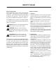
SAFETY RULES Safety Procedures General Information This manual will assist you in the safe operation and proper maintenance of your Husqvarna equipment. Read it thoroughly before attempting to operate the machine. Call your dealer or Husqvarna if additional information is required. 1 - Training: • Read the Operator’s manual. If the operator(s) or mechanic(s) can not read English it is the owner’s responsibility to explain this material to them.
SAFETY RULES 3 - Operation • Never run an engine in an enclosed area. • Only operate in good light, keeping away from holes and hidden hazards. • Slow down and use extra care on hillsides. Make turns gradually and at slow speed. Do not operate across the sides of slopes. Operate up and down slopes only. Do not operate on steep slopes. • Turf conditions can affect the machine’s stability. Do not operate on wet grass where traction may be reduced.
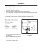
ASSEMBLY Unpacking Instructions 1. 2. 3. 4. 5. 6. 7. 8. Cut plastic tie securing the hitch to the crate top. Remove the top of the crate. Remove the plastic bag. Remove the hose. Remove the sides and ends of the crate. Remove the mounting kit and drive kit boxs from the corner of the crate. Cut the two plastic ties that secure the hitch assembly to the pallet. Remove the hitch assembly. Cut the two plastic ties that secure the back of the hood, and the two that secure the front of the hood.
ASSEMBLY 4. 1 Remove the (10) 5/16 carriage bolts that secure the standard rear guard to the straps and skid plates. Remove the standard rear guard. Replace with the collection rear guard, and secure with the carriage bolts that were just removed. Figure 2. 2 FIGURE 2 1. REAR GUARD 2. STRAP 2 5. Place the hitch assembly on the ground behind the mower. Place the (2) hitch pins thru the hitch and the hitch brackets. Secure the hitch pins with the (2) hairpins that are secured with the (2) lanyards.
ASSEMBLY 7. Place the hood assembly on to the hitch 8. assembly. Place both hood hinges between the upper hitch mounts on the hitch assembly. Be sure that the rubber seal is on the inside of the hood. Place the (2) friction washers between the hood hinge and the upper hitch mount. Place (2)990563, 3/8 x 1 bolt thru the hinge and mount. Secure with (2) 976979, 3/8 nyloc nut. Figure 4. Open the hood and secure the (2) springs to the bolts on the hood assembly and the hitch assembly. Figure 4.
ASSEMBLY 1 9. 10. With the hood open, secure the (3) bags in place. The back of the bags will hook over the mounting tabs on the hitch assembly. Figure 5. Close the hood, and latch the draw latch over the draw latch keeper on the hitch assembly. Figure 5. 2 3 4 5 FIGURE 5 11. 1. 2. 3. 4. 5. Install the (2) linkage assemblies to the (2) support brackets on hitch assembly and the (2) support brackets on the frame. The shorter linkage connects to the support bracket on the hitch assembly. Figure 6.
ASSEMBLY Blower/Drive Kit 1. Open the drive kit box and remove all of the components. 2. Place the deck in the lowest cutting height. 3. Remove the right side belt shield from the deck. 4. Remove the deck belt from the right side pulley. 5. Remove the deck pulley. Note: When the deck pulley is removed, the spindle can fall out of the cutter housing assembly. Be sure to secure the bottom of the spindle so that this does not happen. 6. Place the double pulley on the cutter housing assembly. 7.
OPERATION Operating the Collection System 1. NEVER USE THE COLLECTION SYSTEM WITHOUT THE BLOWER ASSEMBLY AND HOSES SECURELY ATTACHED. 2. Make sure hoses are connected at both ends. Inspect hoses prior to each use. 3. Do not use the unit on slopes greater than 10 degrees. 4. The mower must be running in order to vacuum debris through the mower deck. 5. In heavy grass it may be necessary to mow and collect at a slower ground speed. 6.
SERVICE AND MAINTENANCE Transport For best results, clean poly mesh inside hood regularly. Instructions for doing this can be found in the Service section of this manual. WARNING The collection system bags must be completely empty or removed while driving forward onto a trailer. If the mower must be loaded onto a trailer while there is still debris in the container, the mower must be backed up onto the trailer to avoid tipping.
SERVICE AND MAINTENANCE Caring For Hoses Caring For Bags 1. Inspect hoses before each use. If hoses have excessive wear, tears, or punctures, replace immediately. 2. To prolong the life of the hose, periodically rotate hose and turn hose end to end. Refer to Preventative Maintenance Schedule in this manual. 3. Avoid twists and sharp turns in the hoses, as they will increase wear on the hoses. 4. Avoid dragging the lower hose along the sides of buildings or other hard surfaces.
SERVICE AND MAINTENANCE Troubleshooting Guide DANGER Before servicing unit, wait for all moving parts to come to a complete stop. Turn engine off and remove the spark plug wire. PROBLEM POSSIBLE CAUSE CORRECTION Loss of Vacuum. 1. Blower, hose or hood inlet clogged. 2. Bags full. 3. Fan blades bent or broken. 4. Poly mesh plugged. 1. Remove hose and clean inlet. 2. Inspect and empty. 3. Replace/repair impeller. 4. Clean poly mesh. Unusual vibration or noise. 1. Solid object jammed in unit. 1.
SPINDLE DRIVE ASSEMBLY NOTE: Your Front Weight Bar may look different from those shown in this diagram.
PARTS ILLUSTRATIONS 17
HOOD ASSEMBLY 539 99 06-45 (x 6) 539 99 07-30 (x 2) 539 99 06-13 (x 2) 539 11 11-81 (x 2) 539 11 00-33 (x 8) 539 11 11-72 539 97 69-79 (x 8) 539 11 11-77 (x 2) 539 20 06-84 (x 30) 539 99 05-98 (x 16) 539 97 69-78 (x 8) 539 20 06-84 (x 30) 539 20 06-84 (x 30) 539 99 05-98 (x 16) 539 99 10-03 (x 8) 539 11 11-82 539 11 13-39 539 11 17-55 539 20 06-84 (x 30) 539 11 12-60 539 11 11-83 539 11 11-75 (x 2) 539 10 27-44 (x 11) 539 11 11-86 (x 6) 539 20 04-78 (x 2) 539 97 69-77 (x 6) 539 11 11-86 (x 6) 539
HITCH ASSEMBLY 539 11 11-62 (x 2) 539 99 05-63 (x 20) 539 97 69-79 (x 22) 539 99 05-63 (x 20) 539 11 11-58 (x 2) 539 11 11-87 (x 4) 539 99 05-80 (x 3) 539 99 02-54 (x 4) 539 99 06-25 (x 4) 539 11 11-67 539 11 11-71 539 97 69-79 (x 22) 539 97 69-78 (x 3) 539 97 69-79 (x 22) 539 11 11-57 539 11 12-67 (x 2) 539 99 05-63 (x 20) 539 10 13-31 (x 2) 539 97 69-79 (x 22) 539 10 83-69 (x 2) 539 99 06-55 (x 2) 539 99 06-13 (x 2) 539 11 11-55 539 97 69-79 (x 22) 539 99 05-63 (x 20) 539 97 72-50 (x 2) 539 11 11-9
BLOWER ASSEMBLY 539 10 25-35 539 99 07-17 (x 12) LOCKING COLLAR 539 99 01-96 (x 3) THIS SIDE UP 539 10 26-91 (x 5) 539 10 67-86 (x 2) 539 11 13-31 539 10 57-43 539 10 67-41 539 99 02-08 539 10 81-20 (x 12) 539 10 57-85 539 99 07-17 (x 12) 539 99 00-74 (x 10) 539 88 03-16 (x 7) 539 10 04-72 (x 3) 539 11 13-32 539 10 26-91 (x 5) 539 10 67-86 (x 2) 539 10 26-91 (x 5) 539 88 03-16 (x 7) 539 11 12-27 THIS SIDE DOWN 539 11 12-29 (x 3) 539 99 07-17 (x 12) 539 99 06-92 (x 2) 539 11 17-47 539 11 12-6
BLOWER ASSEMBLY 539 10 81-20 (x 12) 539 99 05-98 (x 12) 539 10 25-63 539 11 12-70 539 11 17-52 539 11 13-28 539 10 81-20 (x 12) 539 99 05-98 (x 12) 539 99 00-74 (x 10) 539 97 69-79 (x 4) 539 99 00-74 (x 10) 21
WEIGHT KIT 539 02 09-21 539 11 13-13 539 10 20-49 (x 2) 539 10 80-96 (x 2) 539 11 12-59 (x 2) 539 97 69-41 (x 4) 539000019 (x 3) 539 99 05-17 (x 4) 539 97 69-79 (x 4) 22
MOUNTING KIT 539 10 29-98 (x 2) 539 97 69-79 (x 6) 539 99 05-63 (x 6) 539 99 06-54 (x 2) 539 11 12-08 (x 2) 539 11 12-07 (x 2) REF.
BAG ASSEMBLY 539 11 00-63 539 99 07-17 (x 7) 539 99 03-16 (x 7) 539 11 11-66 539 99 07-99 (x 7) 539 99 06-92 (x 3) 539 99 07-17 (x 7) 539 11 11-68 24
DRIVE KIT ASSEMBLY (539) 111749 - 72 INCH DECK 539 11 07-40 (x 2) 539 11 17-51 539 10 57-43 539 10 96-60 539 10 57-44 539 97 69-98 539 10 89-51 539 11 13-44 25
PARTS DESCRIPTION PART NUMBER DESCRIPTION 539 02 09-21 539 09 70-76 539 10 01-41 539 10 04-13 539 10 04-72 539 10 13-31 539 10 13-31 539 10 17-21 539 10 20-49 539 10 20-67 539 10 22-44 539 10 25-35 539 10 25-63 539 10 25-63 539 10 26-91 539 10 27-44 539 10 29-98 539 10 54-08 539 10 57-43 539 10 57-44 539 10 57-85 539 10 65-04 539 10 67-13 539 10 67-21 539 10 67-41 539 10 67-86 539 10 80-96 539 10 81-20 539 10 83-69 539 10 87-36 539 10 89-51 539 10 96-60 539 10 99-01 539 11 00-33 539 11 00-63 539 11 07-40
PARTS DESCRIPTION PART NUMBER DESCRIPTION 539 11 11-87 539 11 11-90 539 11 11-91 539 11 11-92 539 11 11-97 539 11 11-99 539 11 12-06 539 11 12-07 539 11 12-08 539 11 12-10 539 11 12-12 539 11 12-15 539 11 12-18 539 11 12-25 539 11 12-27 539 11 12-29 539 11 12-59 539 11 12-60 539 11 12-65 539 11 12-67 539 11 12-70 539 11 13-13 539 11 13-22 539 11 13-28 539 11 13-31 539 11 13-32 539 11 13-39 539 11 13-40 539 11 13-44 539 11 17-46 539 11 17-47 539 11 17-51 539 11 17-52 539 11 17-55 539 20 02-82 539 20 04-78
PARTS DESCRIPTION PART NUMBER DESCRIPTION 539 99 02-47 539 99 02-54 539 99 03-16 539 99 05-17 539 99 05-46 539 99 05-63 539 99 05-80 539 99 05-85 539 99 05-98 539 99 06-13 539 99 06-22 539 99 06-25 539 99 06-45 539 99 06-54 539 99 06-55 539 99 06-92 539 99 07-17 539 99 07-30 539 99 10-03 ER92531 LOCKWASHER, 7/16 WASHER, 1/2 RHSNB 5/16-18 X 5/8, GR5 WASHER, 3/8 NUT, 3/8, CENTERLOCK HCS, 3/8-16 x 1, GR5 HCS, 1/4-20 X 3/4 NUT, 5/16C WASHER, 1/4 NUT, 3/8C HFS, 1/2-13 X 1 1/2 NUT, 1/2, JAM RHSNB, 3/8-16 X 1 C