2007 Utility Vehicles Gasoline and Diesel Owner’s Manual HUV 4421G HUV 4421GXP HUV 4421D HUV 4421DXP
NOTICE Warranty information appears on the last pages of this manual. No other warranties, express or implied, are contained herein. Your authorized representative checked the vehicle before it was delivered to you and will provide you a copy of the completed vehicle warranty registration form. Husqvarna is not liable for errors in this manual or for incidental or consequential damages that result from the use of the material in this manual.
FOREWORD Thank you for choosing Husqvarna, a world leader in outdoor products. You have chosen the finest utility vehicle on the market. Please protect your investment and ensure that your Husqvarna vehicle provides years of reliable, superior performance by reading and following the maintenance instructions in this manual. Your comfort and safety are important to us, so we urge you to read and follow the step-by-step operating instructions and safety procedures in this manual.
TABLE OF CONTENTS Safety Details ............................................................................................................................................ 7 General Warnings ...................................................................................................................................... 8 General Information ................................................................................................................................... 10 Model Identification ..
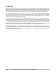
Vehicle Feature Identification ALL HUV 4421 MODELS DIESEL WARNING DECAL GASOLINE WARNING DECAL (DIESEL VEHICLES ONLY, ON PASSENGER-SIDE SEAT SUPPORT) (GASOLINE VEHICLES ONLY, ON PASSENGER-SIDE SEAT SUPPORT) OPERATING INSTRUCTIONS (ON INSTRUMENT PANEL) HOT MANIFOLD WARNING DECAL (ON ENGINE VALVE COVER) WINCH CABLE WARNING DECAL (FOR VEHICLES WITH WINCH ACCESSORY) FRAME GROUND WARNING DECAL (ON VEHICLE FRAME NEAR BATTERY) (ON FRONT BODY) HOT SURFACE WARNING DECAL (ON COOLANT PIPES AND UNDERSIDE OF B
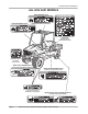
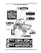
Vehicle Feature Identification ALL HUV 4421 MODELS UNDERAGE WARNING DECAL ! WARNING • Do not modify or remove Roll-over Protective Structure (ROPS). • Replace ROPS if damaged. Do not attempt repair. • Use seat belts during operation. Do not jump from vehicle. • Keep away from drop-offs, steep slopes, and unstable surfaces.
Vehicle Feature Identification Page 6 2007 HUV 4421 Gasoline and Diesel Vehicle Owner’s Manual
Safety Details SAFETY DETAILS ý WARNING • This owner’s manual should be read completely before attempting to drive or service the vehicle. Failure to follow the instructions in this manual could result in property damage, severe personal injury, or death. It is important to note that some vital statements throughout this manual and on the decals affixed to the vehicle are preceded by the words DANGER, WARNING, or CAUTION.
General Warnings GENERAL WARNINGS The following safety statements must be heeded whenever the vehicle is being operated, repaired, or serviced. Safety decal identification information is also included beginning on page 4. Other specific safety statements appear throughout this manual and on the vehicle. ý DANGER • Battery – Explosive gases! Do not smoke. Keep sparks and flames away from the vehicle and service area. Ventilate when charging or operating vehicle in an enclosed area.
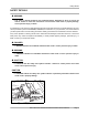
General Warnings ý WARNING • Only trained technicians should service or repair the vehicle. Anyone doing even simple repairs or service should have knowledge and experience in electrical and mechanical repair. The appropriate instructions must be used when performing maintenance, service, or accessory installation. • To avoid unintentionally starting the vehicle: - Disconnect battery cables, negative (–) cable first (Figure 1). - Gasoline vehicles only: Disconnect the spark plug wires from the spark plugs.
General Information GENERAL INFORMATION This manual includes operating procedures, maintenance, and regular servicing information for HUV 4421G, HUV 4421D, HUV 4421GXP, and HUV 4421DXP gasoline and diesel vehicles. All operating procedures, maintenance, and regular servicing are identical unless otherwise noted. MODEL IDENTIFICATION The serial number of each vehicle is printed on a bar code decal mounted on the frame above the brake pedal (Example: RC0601-123456) (Figure 3).
Controls and Indicators 9 8 A 0 1/2 1 1 10 6 OPERATING INSTRUCTIONS 12 B OFF ON START C 14 15 13 4 5 11 7 1 3 2 Figure 4 Instrument Panel – Gasoline Vehicles 9 8 A 0 1/2 1 1 10 6 10 OPERATING INSTRUCTIONS B PREHEAT OFF ON START 12 C 13 15 11 7 4 5 1 3 2 Figure 5 Instrument Panel – Diesel Vehicles 2007 HUV 4421 Gasoline and Diesel Vehicle Owner’s Manual Page 11
Controls and Indicators KEY SWITCH – GASOLINE VEHICLES The key switch (7) is mounted on the instrument panel to the right of the steering column (Figure 4, Page 11). It has three positions: OFF, ON, and START. To start the vehicle, place the Forward/Reverse handle in the NEUTRAL position and turn the key to the START position, and hold it there until the engine starts. Activate the choke (14) as necessary. If the engine does not start after 10-15 seconds, release the key and repeat the procedure.
Controls and Indicators BRAKE PEDAL The brake pedal (2) is located to the immediate left of the accelerator pedal (Figure 4 and Figure 5, Page 11). To slow or stop the vehicle, press the brake pedal. PARK BRAKE The park brake pedal (3) is located to the left of the brake pedal (Figure 4 and Figure 5, Page 11). To engage the park brake, first apply pressure to the brake pedal, then firmly press the park brake pedal until it latches into place.
Controls and Indicators LOW OIL WARNING LAMP The low oil warning lamp (9) is located on the instrument panel just to the left of the steering column (Figure 4 and Figure 5, Page 11). If the warning lamp lights up, oil should be checked and added to the engine as necessary before vehicle use continues. The vehicle should never be driven when the low oil warning lamp remains lit. If the warning lamp alternately lights and darkens, the vehicle may be driven, but oil should be added at the first opportunity.
Roll-Over Protective Structure and Safety Belts ROLL-OVER PROTECTIVE STRUCTURE AND SAFETY BELTS All HUV 4421 vehicles are equipped with a Roll-Over Protective Structure (ROPS) and safety belts for each occupant. See following WARNING. ý WARNING • The ROPS must be properly installed before operating the vehicle. Husqvarna strongly urges that the vehicle’s occupants be properly restrained at all times with the safety belts provided. Pregnant woman: Consult your doctor for specific recommendations.
Roll-Over Protective Structure and Safety Belts ý WARNING • After inserting the tab, make sure the tab and buckle are locked and that the belt is not twisted. • Loose fitting safety belts could increase the chance of injury due to sliding under the belt if sudden braking should occur. Keep the safety belt snug and positioned as low on the hip bone as possible. • Use a single safety belt for one person at a time. Do not use a single safety belt for two or more people – this includes children.
Seat Latch and Adjustment 1 Figure 8 Adjust Headrests SEAT LATCH AND ADJUSTMENT The vehicle seat(s) are hinged to allow easy access to the engine compartment. To raise the seat bottom, grasp the rear side of the seat bottom, and pull firmly in a forward/upward direction. See following WARNING. ý WARNING • Make sure seat hinges and latches are securely engaged before operating the vehicle.
Performance Inspection Use the following list as a guide to inspect the vehicle. This list should be used daily and in conjunction with the Performance Inspection and the Periodic Service Schedule on page 29 to ensure that the vehicle is in proper working condition. Any problems should be corrected by a Husqvarna dealer/distributor or a trained technician. • General: All the parts should be in place and properly installed. Be sure that all nuts, bolts, and screws are tight. Check hose clamps for tight fit.
Driving Instructions • Reverse buzzer: The reverse buzzer should sound as a warning when the Forward/Reverse handle is in the REVERSE position. • Steering: The vehicle should be easy to steer and should not have any play in the steering wheel. Be sure the steering wheel adjustment lever is securely locked into position.
Driving Instructions ý WARNING • Do not leave children unattended on vehicle. • Children requiring a child safety seat must not ride on the vehicle. Comply with state and local laws pertaining to child safety. • Operate the vehicle from the driver seat only. • To help prevent falls from the vehicle, remain seated with safety belt fastened and hold on to hand holds at all times. Driver should keep both hands on the steering wheel when the vehicle is in motion.
Driving Instructions 8.2. Diesel vehicles: To preheat glow plugs in cold weather, turn the key to the PREHEAT position and hold it there for 10-15 seconds. Turn the key to the START position and hold it there until the engine starts. If the engine does not start after 10-15 seconds, turn the key to the OFF position and repeat the procedure. Once the engine starts, release the key and it will return to the ON position. The engine will idle in neutral. 9. Release the park brake. 10.
Bed Latch and Prop Rod – HUV 4421G and HUV 4421D Only STOPPING THE VEHICLE To stop the vehicle, release the accelerator pedal and press the brake pedal until the vehicle comes to a complete stop. See following WARNING and CAUTION. ý WARNING • Driving through water may affect the brakes. After driving through water, check effectiveness of the brakes by gently pressing the brake pedal.
Loading and Unloading Cargo Figure 9 Bed Latch Figure 10 Prop Rod LOADING AND UNLOADING CARGO ý WARNING • • • • • • • • • • • • • Firmly engage park brake before loading vehicle. Do not allow riders in the cargo bed. Reduce vehicle load and speed when driving up or down slopes or on uneven terrain. Do not exceed rated vehicle capacity. Rated capacity is for level surfaces only.
Vehicle Load Capacities Gross Trailer Weight Gross trailer weight is the combination of the trailer weight and the trailer load weight. Maximum Payload Capacity The maximum payload capacity is the maximum amount of load that the vehicle can haul in the cargo bed and/or tow in a trailer. The combined weight of bed load and gross trailer weight cannot exceed the vehicle’s stated maximum payload capacity.
Towing with the Vehicle TOWING WITH THE VEHICLE ý WARNING • • • • • • Do not tow a vehicle or trailer on public streets or highways. Normal vehicle operating speed should be reduced when towing. Extreme caution should be used when towing. Do not allow riders in the vehicle or trailer being towed. Avoid sudden starts, sudden stops, and tight turns when towing. Avoid stopping on a hill when towing. If you must stop on a hill, avoid sudden starts, or rolling backwards and stopping suddenly.
Storage STORAGE See General Warnings on page 8. ý DANGER • Do not attempt to drain fuel when the engine is hot or while it is running. • Clean up any spilled fuel before operating the vehicle. • Store fuel in an approved fuel container only. Store in a well-ventilated area away from sparks, open flames, heaters, or heat sources. • Keep fuel out of the reach of children. • Do not siphon fuel from the vehicle.
Storage FULL OPEN (ON) POSITION PARTIALLY CLOSED POSITION VIEWED FROM SELECTOR SIDE OF VALVE VIEWED FROM SELECTOR SIDE OF VALVE Figure 13 Fuel Shut-off Valve – Open Position Figure 14 Fuel Valve – Partially Closed Position PREPARING THE VEHICLE FOR EXTENDED STORAGE 1. Unload the vehicle so that the tires are supporting only the weight of the vehicle. 2. Store the vehicle in a cool, dry place. This will minimize battery self-discharge.
Maintenance 9. The battery should be clean and free of corrosion. Wash the battery top and terminals with a solution of baking soda and water (1 cup (237 mL) baking soda per 1 gallon (3.8 L) of water). Rinse the solution off the battery. Do not allow this solution to enter the battery. Be sure the terminals are tight. Let the terminals dry and then coat them with Battery Terminal Protector Spray (P/N 603 00 00-03). 10. Adjust the tires to the recommended tire pressure. See Vehicle Specifications on page 50.
Periodic Service Schedule ý WARNING • Only trained technicians should service or repair the vehicle. Anyone doing even simple repairs or service should have knowledge and experience in electrical and mechanical repair. The appropriate instructions must be used when performing maintenance, service, or accessory installation. • If any problems are found during scheduled inspection or service, do not operate vehicle until repairs are made.
Periodic Service Schedule NOTE: If the vehicle is constantly subjected to heavy use or severe operating conditions, the preventive maintenance procedures should be performed more often than recommended in the Periodic Service and Lubrication Schedule. Both the Periodic Service Schedule and the Periodic Lubrication Schedule must be followed to keep vehicle in optimum operating condition.
Periodic Service Schedule PERIODIC SERVICE SCHEDULE REGULAR INTERVAL Semiannual service by trained technician only (or every 50 hours of operation, whichever comes first) SERVICE Battery Clean terminals and wash dirt from casing; check electrolyte level. Add distilled water if necessary. See page 45. Front wheel alignment and toe-in Check and adjust if necessary. See Section 7 – Steering and Front Suspension in the appropriate maintenance and service manual.
Periodic Lubrication Schedule PERIODIC LUBRICATION SCHEDULE PERIODIC LUBRICATION SCHEDULE LUBRICATION POINTS REGULAR INTERVAL SERVICE Gasoline vehicle: First change 20 hours – Diesel vehicle: First change 50 hours – additional change for both every 100 hours of operation or annually, whichever comes first. Change engine oil and oil filter 1 Gasoline vehicles: 1 qt. and 25 oz (1.7 L) with filter Diesel vehicles: 3 qt. (2.8 L) with filter See Oil Viscosity on page 39.
Brake Fluid Reservoir FLOORBOARD 3 4 1 5 7 6 4 2 2 Figure 16 Lubrication Points – Diesel Vehicles BRAKE FLUID RESERVOIR FULL LEVEL MA X 1 SAFE LEVEL MA 2 X MIN MIN MA X MIN Figure 17 Brake Fluid and Coolant Access (diesel vehicle shown) LOW LEVEL Figure 18 Brake Fluid Reservoir The brake fluid reservoir (1) is located under the hood (Figure 17). Raise the hood to check the brake fluid level.
Engine Oil BRAKE FLUID Brake fluid level should be within 1/4-inch (6 mm) from the top of the reservoir (Figure 18). Also, brake fluid should be clean with no residue in the bottom of the reservoir or other evidence of contamination. ý CAUT ION • Use only DOT 5 (silicone) brake fluid. Use of any other type brake fluid is not recommended. ENGINE OIL Even though the low oil warning lamp on the instrument panel should illuminate if the oil level becomes low, the engine oil level should be checked daily.
Engine Oil 2 1 3 3 2 1 Full Level Safe Level Full Level Low Level Safe Level Low Level Figure 19 Engine Oil Level Check – Gasoline Vehicles 1 2 Figure 20 Engine Oil Level Check – Diesel Vehicles With Passenger-side Dipstick 3 Full Level Safe Level Low Level Figure 21 Engine Oil Level Check – Diesel Vehicles With Driver-side Dipstick ENGINE OIL AND FILTER CHANGE Engine oil and oil filter should be changed after the first 20 hours of operation (gasoline) or 50 hours of operation (diesel).
Engine Oil Engine Oil Draining 1. Turn the key switch to the OFF position and remove the key. Place the Forward/Reverse handle in the NEUTRAL position. Chock the front wheels. 2. Disconnect the battery cables, negative (–) cable first. See WARNING “To avoid unintentionally starting...” on page 10. 3. Remove the oil filler cap to allow the oil to drain properly. 4. Position a pan designed for oil changes under the drain plug (Figure 23 or Figure 24, Page 36). 5.
Engine Oil 2 Figure 24 Replace Engine Oil Filter – Gasoline Vehicles Engine Oil Filter Change 1. Drain the engine oil. See Engine Oil Draining on page 36. 2. Place the oil drain pan under the engine oil filter (2) (Figure 23 or Figure 24, Page 37). 3. Remove the engine oil filter. Turn it counterclockwise and drain the residual oil in the filter port and filter into the oil drain pan. See following NOTE.
Engine Oil 4. Use a clean, lint-free rag to wipe the oil filter port flange surface clean where the oil filter gasket seats. 5. To help seal the new oil filter to the oil port flange, apply a light coat of white lithium NLGI Number 2 grease (Dow Corning® BR2-Plus or equivalent) or new engine oil to the rubber seal around the outside surface of the filter before attaching it to the oil filter port (Figure 26, Page 37).
Gearcase Lubrication OIL VISCOSITY Choose the viscosity according to the temperature as shown in the appropriate oil viscosity chart (Figure 29 or Figure 30). See following NOTE. NOTE: Use engine oil with API classification SJ for gasoline engines and CF for diesel engines. Using multi-grade oils (5W-20, 10W-30, and 10W-40) will increase oil consumption. If multi-grade oil is used, check the oil level more frequently.
Gearcase Lubrication 1 1 2 2 Figure 31 Front Differential Lubrication Level Figure 32 Transmission Lubrication Level Transmission: Clean and install the drain plug (2) before filling the transmission with new lubricant (Figure 32). Tighten the drain plug to 8 ft-lb (11 N·m). Remove the fill plug from the top of the transmission case and use a funnel to fill the transmission with lubricant. See Periodic Lubrication Schedule on page 32.
Engine Coolant – Diesel Vehicles ENGINE COOLANT – DIESEL VEHICLES ENGINE COOLANT LEVEL CHECK The coolant reserve tank (2) is located under the hood on the passenger side (Figure 17). Raise the hood to check the coolant level before every operation. 1. Check the coolant level of the reserve tank (2). If the coolant is at or below the LOW mark, add pre-mixed coolant until the level reaches the FULL mark. If a leak is detected, have it checked by a trained technician. See following WARNING.
Fueling Instructions 1 Figure 34 Air Filter Cartridge Air Filter Installation 1. Push the new air filter cartridge onto the nozzle inside the canister. 2. Place the canister cap, marked TOP, on the top center of the canister. 3. Secure the canister cap with both tab locks. FUELING INSTRUCTIONS See General Warnings on page 8. ý DANGER • Turn key switch to the OFF position before fueling. • Never pour fuel into the fuel tank when the engine is hot or while it is running.
Fueling Instructions TO FUEL FILTER FUEL SHUTOFF VALVE TO FUEL FILTER VENT VENT Figure 35 Fuel Tank – Gasoline Vehicles Figure 36 Fuel Tank – Diesel Vehicles Biodiesel Fuel (Diesel Vehicles Only) Biodiesel fuel has unique qualities that should be considered before it is used in the Kubota D722 diesel engine. Review the warranty section for warranty information. During cold weather, plugged fuel lines, plugged fuel systems, hard starting, and other unknown failures can result from use of this fuel.
Fueling Instructions NOTE: Biodiesel fuel does not have long-term stability and must not be left in engines longer than three months. This fuel type attracts moisture and may contain higher water content than conventional diesel fuel. Fuel system maintenance, cleaning, and fuel line replacement are required more frequently for engines that are operated with Biodiesel fuel. DRAINING WATER FROM FUEL FILTER Diesel Vehicles Only Water should be drained from the fuel filter daily.
Battery BATTERY See General Warnings on page 8. ý DANGER • Battery – Explosive gases! Do not smoke. Keep sparks and flames away from the vehicle and service area. Ventilate when charging or operating vehicle in an enclosed area. Wear a full face shield and rubber gloves when working on or near batteries. • Battery – Poison! Contains acid! Causes severe burns. Avoid contact with skin, eyes, or clothing. Antidotes: - External: Flush with water. Call a physician immediately.
Using A Booster Battery (Jump Starting) 3. Disconnect the battery cables, negative (–) cable first. See WARNING “To avoid unintentionally starting...” on page 9. 4. Use a flat-blade screwdriver, and carefully remove the battery cell caps from the battery. See following WARNING. ý WARNING • Wear safety glasses or approved eye protection when servicing the vehicle. Wear a full face shield and rubber gloves when working on or near batteries. 5.
Cleaning the Vehicle 5. Connect the end of the first cable (1) to the positive (+) terminal of the booster battery. Connect the other end of the same cable (2) to the positive terminal of the vehicle battery. See DANGER “Battery – Explosive gases!...” on page 8. 6. Connect the end of the second cable (3) to the negative (–) terminal of the booster battery. Connect the other end of the same cable (4) to the battery frame ground. 7. Sit in the driver’s seat and start the engine. 8.
Accessories ACCESSORIES There is a complete line of accessory equipment available from Husqvarna and our dealers/distributors. You can obtain the name and phone number of your closest Husqvarna contact by visiting our web site at www.usa.husqvarna.com. Care should be taken that these accessories are properly installed by trained technicians and that they are used in the manner for which they were designed. See following WARNING and CAUTION.
Subsequent Owner Registration ý WARNING • To avoid the risk of rollover when operating a vehicle equipped with mud tires on a paved surface: reduce speed, use extreme caution, and drive slowly in turns. Husqvarna tires are made specifically for the AWD vehicle; therefore, Husqvarna recommends that only tires purchased from Husqvarna be used on your AWD vehicle.
Vehicle Specifications VEHICLE SPECIFICATIONS SPECIFICATIONS HUV 4421G Gasoline HUV 4421D Diesel HUV 4421GXP Gasoline HUV 4421DXP Diesel POWER SOURCE Engine: 4-cycle OHV, 614 cc, 20.0 maximum HP @3600 rpm (per SAE J 1940/ 1349), twin-cylinder, air-cooled, with pressure lubrication system • Engine: 4-cycle OHV, 719 cc, 20.
Vehicle Specifications SPECIFICATIONS HUV 4421G Gasoline HUV 4421D Diesel HUV 4421GXP Gasoline HUV 4421DXP Diesel BODY/CHASSIS, CONTINUED Gasoline Diesel Gasoline Diesel *Weight: Gasoline with electric bed lift, mud tires, and without brush guard Diesel with electric bed lift, mud tires, and brush guard 1450 lb. (657.6 kg) 1597 lb. (724.2 kg) 1450 lb. (657.6 kg) 1597 lb. (724.2 kg) Forward speed 25 mph (40 km/h) Governed RPM 3825 Load bed height 34 in. (86.4 cm) 48.0 x 49.8 x 10.9 in.
HUSQVARNA® LIMITED TWO YEAR WARRANTY FOR 2007 TRANSPORTATION AND UTILITY VEHICLES 1. WARRANTY: Husqvarna, INC.
6. DISCLAIMER: THIS LIMITED WARRANTY IS EXCLUSIVE. HUSQVARNA MAKES NO OTHER WARRANTY OF ANY KIND, EXPRESSED OR IMPLIED. ANY IMPLIED WARRANTIES OF MERCHANTABILITY OR FITNESS FOR A PARTICULAR PURPOSE WHICH EXCEED THE OBLIGATIONS OR TIME LIMITS STATED IN THIS WARRANTY ARE HEREBY DISCLAIMED BY HUSQVARNA AND EXCLUDED FROM THIS WARRANTY. THE PURCHASER AND HUSQVARNA EXPRESSLY AGREE THAT THE REMEDY OF THE REPLACEMENT OR REPAIR OF THE DEFECTIVE VEHICLE OR COMPONENT THEREOF IS THE SOLE REMEDY OF THE PURCHASER.
TECHNICAL & CONSUMER INFORMATION (GASOLINE ENGINES) Carburetor Modification for High Altitude Operation At high altitude, the standard carburetor air-fuel mixture will be too rich. Performance will decrease, and fuel consumption will increase. A very rich mixture will also foul the spark plug and cause hard starting. Operation at an altitude that differs from that at which this engine was certified, for extended periods of time, may increase emissions.
Emission Control System Information Source of Emissions The combustion process produces carbon monoxide, oxides of nitrogen, and hydrocarbons. Control of hydrocarbons and oxides of nitrogen is very important because, under certain conditions, they react to form photochemical smog when subjected to sunlight. Carbon monoxide does not react in the same way, but it is toxic. Honda utilizes lean carburetor settings and other systems to reduce the emissions of carbon monoxide, oxides of nitrogen and hydrocarbons.
CALIFORNIA EMISSION CONTROL WARRANTY STATEMENT Your new Husqvarna, Inc. ("Husqvarna") vehicle engine complies with both the U.S. EPA and State of California emission regulations. YOUR WARRANTY RIGHTS AND OBLIGATIONS: The California Air Resources Board ("CARB") and Husqvarna are pleased to explain the emission control system warranty on your 2007 vehicle engine. In California, new small off-road engines (SORE) must be designed, built and equipped to meet the State's stringent anti-smog standards.
Husqvarna Part Number 531 30 81-86 Edition Code 0706A00000 CCI P/N 103218307