
Lawn Mower Accessory User Manual


3
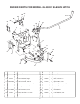
FIGURE 2B
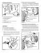
CARTON CONTENTS
1. Sleeve Hitch Frame Assembly
2. Mounting Bracket (R.H.)
3. Mounting Bracket (L.H.)
4. Lifting Link Plate
5. Hitch Pin
6. Lift Lever Assembly (with R.H. Pivot Bracket)
7. L.H. Pivot Bracket
8. Sleeve Hitch Lift Assembly
ORIGINAL NUT
LEFT MOUNTING
BRACKET
3/8" FLAT WASHER
(TOP HOLE ONLY)
REMOVE NUTS
FROM BOLTS
RIGHT MOUNTING
BRACKET
3/8" LOCK WASHER
(If new bolt and nut are needed)
FIGURE 1
1
3
4
5
6
2
7
8
TOOLS REQUIRED FOR ASSEMBLY
(1) 1/2" Wrench or Adjustable Wrench
(2) 9/16" Wrenches or Adjustable Wrenches
(1) 15/16" Wrenches or Adjustable Wrenches
1. Assemble a 5/16" x 1" hex bolt, a spacer and a 5/16"
nylock nut to the three position slot in the R.H. pivot
bracket on the left lever assembly. Use the position
closest to the bend in the bracket (lowest implement
depth setting). See fi gure 1.
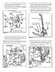
IF YOUR TRACTOR LOOKS LIKE FIGURE 2B
3. Remove the nuts from the two bolts in each side of the
tractor, leaving the bolts in place. See fi gure 2B.
4. Attach the left (LH) and right (RH) Mounting Brackets to
the bolts using the original nuts and two 3/8" fl at washers.
The brackets should angle outward with the weld pins
at the top of the brackets facing inward. See fi gure 2B.
NOTE:
If no bolt and nut are present in a hole, use a 3/8" x
1-1/4" hex bolt, 3/8" lock washer and 3/8" hex nut to attach
the Mounting Bracket to the hole.
5/16" X 1"
HEX BOLT
5/16" NYLOCK
NUT
SPACER
PIVOT
BRACKET
ASSEMBLY
IF YOUR TRACTOR LOOKS LIKE FIGURE 2A
2. Install two 3/8" x 1-1/4" hex bolts in the left side of the
tractor as shown. Attach the left (L.H.) Mounting Bracket
(pin at top facing in) to the bolts using two 3/8" lock
washers and 3/8" hex nuts. Repeat on the right side.
See fi gure 2A.
3/8" HEX NUT
3/8" LOCK WASHER
LEFT MOUNTING BRACKET
3/8" x 1-1/4"
HEX BOLT
RIGHT MOUNTING BRACKET
FIGURE 2A