Operator′s manual K750 Please read the operator’s manual carefully and make sure you understand the instructions before using the machine.
KEY TO SYMBOLS Key to symbols WARNING! The machine can be a dangerous tool if used incorrectly or carelessly, which can cause serious or fatal injury to the operator or others. Stop, with the return spring to the operating position. Stop, in the fixed position. Please read the operator’s manual carefully and make sure you understand the instructions before using the machine.
CONTENTS Contents KEY TO SYMBOLS Key to symbols ............................................................. CONTENTS Contents ...................................................................... WHAT IS WHAT? What is what on the power cutter? ............................... SAFETY INSTRUCTIONS Steps before using a new power cutter. ....................... Personal protective equipment ..................................... Machine′s safety equipment ........................................
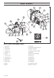
WHAT IS WHAT? 1 2 3 4 5 17 6 16 15 7 13 14 12 11 10 9 8 24 18 19 20 21 22 23 26 25 What is what on the power cutter? 1 Front handle 14 Fuel tank 2 Water tap 15 Automatic decompression valve 3 Warning decal 16 Guard for the blade 4 Air filter cover 17 Adjustment handle for guard 5 Cylinder cover 18 Belt guard 6 Choke 19 Water connection with filter 7 Throttle lockout 20 Cutting arm 8 Throttle control 21 Rating plate 9 Start throttle lock 22 Belt tensioner 10 Stop
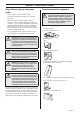
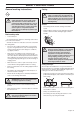
SAFETY INSTRUCTIONS Steps before using a new power cutter. • Please read the operator’s manual carefully. • Check the cutting blade’s mounting, see the chapter ”Assembly”. • Start the engine and check the idling setting, see instructions under the heading Maintenance. When the carburettor is set correctly the cutting blade should be still while idling. Setting of the idle speed is described in the Operator’s Manual. Set the correct speed according to these instructions.
SAFETY INSTRUCTIONS Machine′s safety equipment This section describes the machine′s safety equipment, its purpose, and how checks and maintenance should be carried out to ensure that it operates correctly. See the ”What is what?” section to locate where this equipment is positioned on your machine. ! WARNING! Never use a machine that has faulty safety equipment! Carry out the inspection, maintenance and service routines listed in this section.
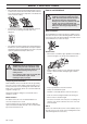
SAFETY INSTRUCTIONS Checking, maintaining and servicing the machine′s safety equipment ! WARNING! All servicing and repair work on the machine requires special training. This is especially true of the machine′s safety equipment. If your machine fails any of the checks described below you must contact your service agent. When you buy any of our products we guarantee the availability of professional repairs and service.
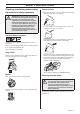
SAFETY INSTRUCTIONS General safety precautions • • A power cutter is designed to cut hard materials, such as masonry. Observe the increased risk of kickback when cutting soft materials. See instructions under the heading How to avoid kickback. Do not use the power cutter until you have read the entire contents of this Operator’s Manual.
SAFETY INSTRUCTIONS General working instructions Cutting ! ! WARNING! This section describes basic safety directions for using a power cutter. This information is never a substitute for professional skills and experience. If you get into a situation where you feel unsafe, stop and seek expert advice. Contact your dealer, service agent or an experienced power cutter user. Do not attempt any task that you feel unsure of! General • Start cutting with the machine running at maximum speed.
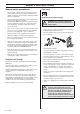
SAFETY INSTRUCTIONS • • Move the blade slowly forwards and backwards to achieve a small contact area between the blade and the material to be cut. This reduces the temperature of the blade and ensures effective cutting. Feed down the machine in line with the blade. Pressure from the side can damage the blade and is very dangerous. How to avoid kickback ! WARNING! Kickback can happen very suddenly and violently; kicking the power cutter and cutting blade back at the user.
SAFETY INSTRUCTIONS Pinching/rotation If the cut is pressed together this can lead to jamming. The machine can be pulled down suddenly with a very powerful jerk. Water cooling ! How to avoid pinching Support the work piece in such a way that the cut remains open during the cutting operation and when the cut is finished. WARNING! Water cooling, which is used when cutting concrete, cools the blade and increases its service life while also reducing the formation of dust.
SAFETY INSTRUCTIONS Ensure the blade it not cracked or damaged in any other way. Diamond blades for dry cutting Diamond blades for dry cutting are a new generation of blades that do not require water cooling. However, the blades will still be damaged by excessive heat. It is most economical to allow the blade to cool by simply lifting it out from the cut every 30–60 seconds and letting it rotate in the air for 10 seconds.
ASSEMBLY Checking the drive axle and flange washers The shaft can be locked using a screwdriver, steel pin or the like. This is slid in as far as possible. The blade is tightened clockwise. Check that the threads on the drive shaft are undamaged. Check that the contact surfaces on the blade and the flange washers are undamaged, of the correct dimension, clean, and that they run properly on the drive axle.
FUEL HANDLING Fuel • Mix (shake) the fuel mixture thoroughly before filling the machine’s fuel tank. • Do not mix more than one month’s supply of fuel at a time. • If the machine is not used for some time the fuel tank should be emptied and cleaned. CAUTION! The machine is equipped with a two-stroke engine and must always been run using a mixture of petrol and twostroke engine oil. It is important to accurately measure the amount of oil to be mixed to ensure that the correct mixture is obtained.
STARTING AND STOPPING Starting and stopping ! WARNING! Note the following before starting: Do not start the power cutter without the belt guard fitted. Otherwise the clutch could come loose and cause personal injuries. Always move the machine away from the refuelling area before starting. Starting ! WARNING! The cutting blade rotates when the engine is started. Make sure it can rotate freely. Grip the front handle with your left hand.
MAINTENANCE Tensioning the drive belt • • • • The cutting head is now loose and can be removed from the machine. Remove the rear belt guard by releasing the two screws holding the guard. • Replace the drive belt. • Assemble in the reverse order as set out for dismantling. • Check that the guard over the cutting blade is not cracked or damaged in any other way. Replace when damaged. The drive belt is fully enclosed and well protected from dust and dirt.
MAINTENANCE Fuel filter • The fuel filter sits inside the fuel tank. • The fuel tank must be protected from contamination when filling. This reduces the risk of operating disturbances caused by blockage of the fuel filter located inside the tank. • The filter cannot be cleaned but must be replaced with a new filter when it is clogged. The filter should be changed at least once per year. Put the filter in a plastic bag and pour the filter oil over it. Knead the plastic bag to distribute the oil.
MAINTENANCE • Pull the cord out about 30 cm and lift it into the cut-out in the periphery of the starter pulley. When the cord is intact: Release the spring tension by letting the pulley rotate slowly backwards. Tensioning the recoil spring • Hook the starter cord in the notch in the pulley and turn the starter pulley about 2 turns clockwise. Changing a broken recoil spring Remove any remnants of the old starter cord and check that the return spring works.
MAINTENANCE Fitting the starter • To fit the starter, first pull out the starter cord and place the starter in position against the crankcase. Then slowly release the starter cord so that the pulley engages with the pawls. Cooling system To keep the working temperature as low as possible the machine is equipped with a cooling system. The cooling system consists of: 5 4 • 3 Tighten the screws. Spark plug 2 1 The spark plug condition is influenced by: 1 Air intake on the starter.
MAINTENANCE General maintenance instructions Below you will find some general maintenance instructions. If you have more questions, contact your service agent. 4 8 12 9 3 10 19 15 17 5 18 6 16 2 14 13 17 7 11 Daily maintenance 1 Check that the components of the throttle control work smoothly (throttle control and throttle trigger lock). 2 Check the tension of the drive belt. 3 Check the condition of the blade and the drive gear. 4 Check the condition of the blade guard.
TECHNICAL DATA Engine Cylinder displacement, K750 cm3 74 Cylinder bore, mm 51 Stroke, mm 36 Idle speed, rpm 2700 Recommended max.
TECHNICAL DATA EC-declaration of conformity (Applies to Europe only) Husqvarna Construction Products, SE-433 81 Partille, Sweden, tel: +46-31-949000, declares under sole responsibility that the power cutter K750 from year 2006 serial numbers and onward (the year is clearly stated in plain text on the rating plate with subsequent serial number) conforms with the requirements of the COUNCIL’S DIRECTIVE: • of June 22, 1998 ”relating to machinery” 98/37/EC, annex IIA.
1150287-26 ´®z+R