6 Operator’s Manual − Model LE389 Read and keep this book for future reference. This book contains important information on SAFETY, ASSEMBLY, OPERATION, AND MAINTENANCE. PRODUCT INFORMATION The owner must be certain that all the product information is included with the unit. This information includes the INSTRUCTION BOOKS, the REPLACEMENT PARTS and the WARRANTIES. This information must be included to make sure state laws and other laws are followed. MS-3616MA 4.
Congratulations... Thank you for purchasing this quality Husquvarna product. We understand that there are many brands today from which you may choose, and we’re pleased that you’ve placed your confidence in the Husquvarna brand. When operated and maintained according to the Operator’s Manual, we believe this product will deliver many years of reliable service.
Safety . . . . . . . . . . . . . . . . . . . . . . . . . . . . . . . . . . . . . . . . . . . . . . Symbols And Warnings . . . . . . . . . . . . . . . . . . . . . . . . . . . . . . . . . . . . . . . . . . Operator Safety Rules . . . . . . . . . . . . . . . . . . . . . . . . . . . . . . . . . . . . . . . . . . . Parts Packed Separately In Carton . . . . . . . . . . . . . . . . . . . . . . . . . . . . . . . . Removal From The Carton . . . . . . . . . . . . . . . . . . . . . . . . . . . . . . . . . . . . . . .
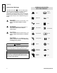
Safety Safety Symbols And Warnings The safety alert symbol is used to identify safety information about hazards that can result in personal injury. A signal word (DANGER, WARNING, or CAUTION) is used with the alert symbol to indicate the likelihood and the potential severity of injury. In addition, a hazard symbol may be used to represent the type of hazard. DANGER indicates a hazard which, if not avoided, will result in death or serious injury.
WARNING When Adding Fuel • Stop the engine. Let engine cool at least 2 minutes before removing the gas cap. • Fill fuel tank outdoors or in well-ventilated area. • Do not overfill fuel tank. Fill tank to approximately 1-1/2 inches below top of neck to allow for fuel expansion. • Keep gasoline away from sparks, open flames, pilot lights, heat, and other ignition sources. • Check fuel lines, tank, cap, and fittings frequently for cracks or leaks. Replace if necessary.
WARNING Safety Rotating parts can contact or entangle hands, feet, hair, clothing, or accessories. Traumatic amputation or severe laceration can result. • • • • • • • • Operate equipment with guards in place. Keep hands and feet away from rotating parts. Tie up long hair and remove jewelry. Do not wear loose-fitting clothing, dangling drawstrings or items that could become caught. Before unclogging the blade or making repairs, stop the engine by moving the throttle control to the stop position.
Operator Safety Rules • • Read the owner’s manual carefully. Be thoroughly familiar with the controls and the proper use of the Edger. Know how to stop the Edger and disengage the controls quickly. • Do not operate the Edger without wearing adequate outer garments. Wear footwear that will improve footing on slippery surfaces. Wear safety glasses or eye shields to protect your eyes from thrown objects. • Keep the area of operation clear of all persons, particularly small children and pets.
Safety Repair / Adjustments Safety • After striking a foreign object, stop the engine. Remove the wire from the spark plug, and keep the wire away from the plug to prevent accidental starting. Thoroughly inspect the Edger for any damage, and repair the damage before restarting and operating. • If Edger should start to vibrate abnormally, stop engine and check immediately for the cause. 6 Vibration is generally a warning of trouble. • Stop the engine whenever you leave the operating position.
Assembly Parts Packed Separately In Carton 1 − Control Rod Assembly 1 − Owner’s Manual (not shown) 1 − Container Of Oil 1 − Upper Handle 1 − Lower Handle 1 − Handle Panel 4 − Wheels 1 − Hardware Parts Bag 1 − Container of Oil The fasteners are shown at full size. The quantities are shown in brackets ( ). NOTE: Some models will not use every fastener shown on this page. Locknut (8) 5/16-18 Washer (4) 11/32 x 11/16 Washer (1) 1/2 x 3/4 Cotter Pin (1) Shoulder Bolt (1) 3/8-16 x 1.
WARNING Assembly Thrown debris can result in foreign objects being thrown into the eyes, which can cause severe eye damage. • Always wear safety glasses or eye shields while you assemble, operate or do maintenance to the unit. Removal From The Carton 1 Remove the lower handle, upper handle, control rod and packing material from the carton. 2 Remove the wheels from the carton. 3 Remove the bottle of oil and the parts bag from the carton. 4 Cut down all four corners of the carton.
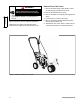
How To Assemble The Handle F For ease of assembly, attach the lower handle before mounting the wheels. 1 Mount the lower handle (A) to the inside of the edger frame (B). Fasten the lower handle with the fasteners (C, D) shown in Figure 3. As you tighten the fasteners, pull back on the lower handle. H Washer 1/2x3/4 Assembly 2 Attach the right rear wheel (E) to the wheel support rod (F) with the fasteners (G, H) shown in Figure 4.
5 Assemble the upper handle (T) and the handle panel (U) to the lower handle (V) with the fasteners (W, X) shown in Figure 7. Make sure the locknuts (X) are on the inside of the lower handle. A Z Assembly 6 Slide one end of the clutch rod (Y) from left to right through the hole in the clutch lever (Z). Secure with the hair pin (A) shown in Figure 7. 7 Move the clutch lever to the first depth position.
Features Know your product: If you understand the unit and how the unit operates, you will get the best performance. As you read this manual, compare the illustrations to the unit. Learn the location and the function of the controls. To help prevent an accident, follow the operating instructions and the safety rules. Keep this manual for future reference. B P E F D H R Q L C G A J I M O N GB K 11 Features K Index Lever − Use the index lever to change the angle of the blade.
Operation Eye Protection Before Starting The Engine Always wear safety glasses. If you wear eye glasses, put a Wide Vision Safety Mask over your eye glasses. WARNING CAUTION This engine was shipped from the factory without oil. If you start the engine without oil, the engine will be damaged beyond repair and will not be covered under warranty. Thrown debris can result in foreign objects being thrown into the eyes, which can cause severe eye damage.
Gasoline Requirements All gasoline is not the same. If a starting or performance problem is encountered after new gasoline has been used, try another service station or change brands. This engine is designed to operate on gasoline. The emission control system for this engine is EM (Engine Modifications). Type of gasoline to use Always use gasoline that meets these requirements: • Clean, fresh, unleaded gasoline.
How To Start The Engine WARNING 2 Move the throttle control lever (B), if equipped, to the FAST position (see Figure 12). Engines give off carbon monoxide, an odorless, colorless, poison gas. Breathing carbon monoxide can cause nausea, fainting or death. 3 Move the choke control lever (C) to the CHOKE position (see Figure 12). • Start and run engine outdoors. • Do not start or run engine in enclosed area, even if doors or windows are open.
4 Hold the recoil starter handle (D) firmly with your right hand (see Figure 13). 5 Hold the edger handle firmly with your left hand. 6 Slowly pull the starter rope handle until resistance is felt, then pull quickly. DO NOT allow the starter rope to snap back. Let the rope slowly rewind. 7 When the engine starts, move the throttle control lever forward to the FAST position to increase speed or back to decrease speed. During normal use, run the engine at full speed .
How To Stop How To Use The Throttle Control Emergency Stopping To immediately stop the engine and the blade, move the throttle control (A), located on the engine, to the stop position (see Figure 14. 1 The throttle control is located on the engine. 2 During normal use, run the engine at full speed (see Figure 14). To immediately stop only the blade, pull the clutch/depth control lever (B) all the way back to raise and disengage the blade (see Figure 15).
How To Use The Clutch/Depth Control Lever WARNING B Thrown debris can cause severe laceration. • Keep a safe distance from rotating blade during operation. The clutch / depth control lever has two blade functions, a clutch and a depth control. When the lever is moved forward, the clutch will first engage the edger blade. Continue to move the lever forward to lower the edger blade and to set the depth of cut. Figure 16: Clutch / Depth Control Lever WARNING 1 Start the engine.
How To Use The Index Lever 1 Stop the engine. Do not change the position of the index lever while the engine is running. 2 Disconnect the spark plug wire from the spark plug. 3 Loosen the front wheel knob (A) shown in Figure 17. Slide the front wheel (B) all the way to the right side. A 4 Securely tighten the front wheel knob. B CAUTION To prevent the blade (C) from hitting the wheel while trimming, make sure the front wheel is set in the extreme right position.
How To Operate The Edger The edger is designed to cut a small trench along sidewalks and driveways or to trim close to trees, flower beds, lampposts, etc. The main reason for edging is to enhance the overall appeal of the yard. A cleanly−edged yard gives a nice, overall finished look. 3 Start the engine. See “How To Start The Engine”. Always dress properly to protect against flying debris. Wear substantial shoes, long pants and close−fitting clothes that are not likely to get caught in the machinery.
Curb-hop feature 1 Stop the engine. Never adjust the wheels while the engine is running. 2 Disconnect the spark plug wire from the spark plug. 8 Use the curb height adjust lever to lower the front wheel to the setting where the front wheel touches the pavement and the unit is level. 9 Connect the spark plug wire to the spark plug. 3 Set the entire unit on the curb level. Loosen the front wheel knob (A). See Figure 21.
Edging Tips • Edging is best performed when conditions are dry. If the soil is too wet, dirt becomes packed around the blade causing premature belt wear and decreased performance. • If dirt does become packed around the blade, stop the engine and remove the wire from the spark plug. Remove the packed dirt and debris from the blade. • For deep edging, first cut at shallow depths. Then, cut at greater depths until the desired depth is obtained.
Maintenance Maintenance Chart PROCEDURE E D G E R E N G I N E Before Each Use First 5 to 8 Hours Lubricate Wheel Axles Check Blade for Wear or Damage √ √ √ Oil, Check √ Tighten All Fasteners Every 50 Hours Every 100 Hours √ √ Lubricate All Pivot Points Drive Belt, Check Every 25 Hours √ Oil, Change *** Cooling System, Clean * Air Filter, Clean / Replace ** Muffler, Check √ √ √ √ √ √ √ √ √ √ √ √ Spark Plug, Clean / Replace Inspect Spark Arrester Before Storage √ √ Maintenance * In dus
How To Remove The Belt The belt (A) is made of a special compound. If the belt becomes worn or breaks, replace the belt with an original equipment belt. D D K 1 Disconnect the spark plug wire from the spark plug. 2 Pull the clutch / depth control lever (B) back to release the tension from the belt (see Figure 22). G F A B E C Figure 22: Clutch / Depth Control Lever Figure 23: Belt Removal Maintenance 3 Remove the two screws (C) and spacers (D) from the top of the engine pulley cover (E).
How To Replace The Blade The blade is subject to wear and damage, such as nicks and dents. This is normal and does not affect its function. The blade does not require sharpening. Do not sharpen the blade. If both sides of the blade (A) are severely worn or damaged, replace as follows. 1 Disconnect the spark plug wire from the spark plug. 2 Remove the blade locknut (B) that holds the blade to the drive shaft. D NOTE: To remove or tighten the blade locknut, always use the method shown in Figure 25.
Engine Maintenance CAUTION All the components used to build this engine must remain in place for the proper operation of this engine. Emission Control Maintenance, replacement or repair of the emission control devices and systems may be performed by any non−road engine repair establishment or individual.
How To Change The Oil Change oil after first 5 to 8 hours of use, then every 50 hours. Change oil every 25 hours when operating the engine under heavy load or in high temperatures. C 1 Disconnect the spark plug wire and keep it away from the spark plug. 2 Clean the area around the oil fill cap (A) and the oil drain plug (B) of dirt and debris. See Figure 27. 3 With engine off but still warm, remove the oil drain plug (B). Completely drain all of the oil from the engine into an appropriate receptacle.
How To Service The Air Filter Replace the air filter every 50 hours; more often in dusty or dirty conditions. WARNING CAUTION Gasoline and its vapors are extremely flammable and explosive. Fire or explosion can cause severe burns or death. Do not use pressurized air or solvents to clean the filter. Pressurized air can damage the filter and solvents will dissolve the filter. 1 Disconnect the spark plug wire from the spark plug.
Storage Follow these guidelines when storing the edger for longer than 30 days. Edger • Completely clean the edger. • Check the edger for worn or damaged parts. Tighten all loose hardware. • Apply a small amount of engine oil to all moving parts, particularly the wheels. • Put the edger in a building that has good ventilation. • Store the Edger in the operating position with the wheels down.
Troubleshooting PROBLEM CAUSE Engine difficult to start CORRECTION Stale fuel Drain fuel tank. Fill with fresh fuel. Dirt in fuel tank or out of fuel Drain and clean fuel tank. Fill with fresh fuel. Carburetor out of adjustment Contact an Authorized Husqvarna service dealer. Fouled spark plug Clean and set spark plug gap. Dirty air filter Clean or replace air filter. Engine smokes excessively Dirty air filter Clean or replace air filter.
GB 31
Product Specifications Product Specifications Model No.: LE389 Horsepower: 4 Displacement: 9.02 cu. in (148 cc) Gasoline Capacity: 1 quart Oil Capacity: 20 oz SAE−30W Spark Plug Gap: 0.030 in Bore: 2-9/16 in (65.09 mm) Stroke: 1-3/4 in (44.45 mm) Armature Air Gap: 0.006−0.010 in (0.15−0.
WARRANTY STATEMENT SECTION 1: LIMITED WARRANTY Warranties Husqvarna Forest & Garden Company (“Husqvarna”) warrants Husqvarna product to the original purchaser to be free from defects in material and workmanship from the date of purchase for the “Warranty Period” of the product as set forth below: Lifetime Warranty (Parts and Labor): All tiller tines and trimmer shafts against breakage. Proof of purchase required.
WARRANTY STATEMENT SECTION 3: ITEMS NOT COVERED BY THIS WARRANTY The following items are not covered by this warranty: 1. Normal customer maintenance items which become worn through normal regular use, including, but not limited to, belts, blades, blade adapters, bulbs, clutches, clutch drums, filters, guide bars, lubricants, rewind springs, saw chain, spark plugs, starter ropes and tines. 2. Natural discoloration of material due to ultraviolet light. 3.
Emissions Control System Warranty Statement Briggs & Stratton Corporation (B&S), the California Air Resources Board (CARB) and the United States Environmental Protection Agency (U.S. EPA) Emissions Control System Warranty Statement (Owner’s Defect Warranty Rights and Obligations) The California Air Resources Board (CARB), U.S. EPA and B&S are pleased to explain the Emissions Control System Warranty on your small off-road engine (SORE).
Look For Relevant Emissions Durability Period and Air Index Information OnYour Engine Emissions Label Engines that are certified to meet the California Air Resources Board (CARB) Tier 2 Emissions Standard must display information regarding the Emissions Durability Period and the Air Index. Briggs & Stratton makes this information available to the consumer on our emissions labels. The engine emissions label will indicate certification information.
MODEL LE389 FACTORY NO. EH4000x37NA ENGINE MOUNT ASSEMBLY 43 40 44 41 45 22 42 20 26 20 24 10 30 29 32 80 81 12 36 Key No. Part No. Description 10 −−−−− Engine 12 601 00 08 35 20 Key No. Part No. Description 40 601 00 22 04 Cover, Engine Pulley Screw, 3/8−16x1.00 41 601 00 00 80 Screw, 5/16−24x3.00 601 00 22 03 Pulley, Half 42 601 00 22 05 Spacer, Sleeve 22 601 00 13 27 Screw, 5/16−24x1.00 43 601 00 22 06 Screw, 5/16−24x3.
MODEL LE389 FACTORY NO. EH4000x37NA WHEEL ASSEMBLY REF. LOWER HANDLE 667 668 669 REF. FRAME 654 651 654 670 654 655 655 680 654 653 Key No. Part No. Description 650 601 00 22 49 Tire & Rim 651 601 00 08 67 653 650 Key No. Part No. Description 667 601 00 22 50 Bolt, SHH 3/8−16 Nut, 5/16−18 668 601 00 22 51 Spacer & Washer 601 00 00 86 Screw, 5/16−18x4.
MODEL LE389 FACTORY NO. EH4000x37NA WHEEL BRACKET ASSEMBLY REF. FRAME ASSEMBLY 163 151 150 152 164 160 157 156 161 153 159 155 154 158 38 Key No. Part No. Description 150 601 00 22 33 Front Wheel Arm 151 601 00 22 34 152 Key No. Part No. Description 157 601 00 20 40 Knob, Rectangle Rod, Front Mount Curb 158 601 00 00 94 Flatwasher 601 00 22 35 Pushnut, Washer 159 601 00 22 41 Nut 153 601 00 22 36 Plastic Washer 160 601 00 22 27 Screw, 5/16−18x.
MODEL LE389 FACTORY NO. EH4000x37NA CURB-HOP ASSEMBLY 184 182 171 183 171 REF. 170 FRAME 172 181 180 172 186 Key No. Part No. Description 170 601 00 06 47 Bracket, Curb Hop Mnt 171 601 00 00 73 172 Key No. Part No. Description 182 601 00 19 71 Spacer, Sleeve Screw, 5/16−18x.75 183 601 00 00 19 Flatwasher 601 00 00 59 Nut, 5/16−18 184 601 00 06 84 Knob, Wing 5/16−18 180 601 00 19 70 Bolt, 5/16−18x2.
MODEL LE389 FACTORY NO. EH4000x37NA EDGER BLADE ASSEMBLY 330 322 331 329 323 321 301 325 302 300 320 311 312 310 REF. SUPPORT BRKT. 305 40 REF. FRAME ASSY. Key No. Part No. Description 300 601 00 00 21 Flatwasher 301 601 00 21 96 302 Key No. Part No.
MODEL LE389 FACTORY NO. EH4000x37NA BLADE GUARD ASSEMBLY 1 2 4 5 9 REF. QUILL ASSY. 6 8 Key No. GB Part No. Description 1 601 00 22 10 Blade Guard 2 601 00 07 86 Bolt, Carriage 5/16−18x.63 4 601 00 08 67 Nut, 5/16−18 5 601 00 22 11 Guide, Belt Front 6 601 00 21 95 Screw, 1/4−20x.50 8 601 00 19 78 Cover, Quill Pulley 9 601 00 24 70 Screw, 10−16x.
MODEL LE389 FACTORY NO. EH4000x37NA CLUTCH / DRIVE LEVER ASSEMBLY 741 737 743 745 731 739 725 738 732 735 42 740 Key No. Part No. Description 725 601 00 21 98 Upper Handle & Foam 731 601 00 22 22 Selector Plate 732 601 00 00 69 Screw, 1/4−20x1.25 735 601 00 23 18 Nut, 1/4−20 737 601 00 22 23 Depth Adjust Handle 738 601 00 19 84 Screw, 5/16−18x1.
MODEL LE389 FACTORY NO. EH4000x37NA HANDLE ASSEMBLY 4 7 9 REF. UPPER HANDLE 3 8 5 2 4 REF. BLADE ASSY. 1 Key No. GB Part No. Description 1 601 00 22 27 Screw, 5/16−18x.63 2 601 00 00 59 Nut, 5/16−18 3 601 00 12 94 Bolt, 5/16−18x1.
MODEL LE389 FACTORY NO. EH4000x37NA DECALS 825 829 823 830 821 826 824 822 820 Key No. Part No. Description 820 601 00 22 00 Decal, Recoil Cover 821 601 00 18 77 Decal, Information Danger 822 44 Reference Only 823 601 00 22 52 Decal, Engine 824 601 00 22 29 Decal, Angle Indicator 825 601 00 22 30 Decal, Quadrant Selector 826 601 00 22 31 Decal, Blade Guard 829 601 00 20 96 Decal, Panel 830 601 00 22 53 Decal, Husqvarna LE389 www.usa.husqvarna.
45
www.usa.husqvarna.