GB ES DE FR Operator’s manual Please read the operator’s manual carefully and make sure you understand the instructions before using the machine. Husqvarna PG680 Bedienungsanweisung PG820 Manual de instrucciones Lea detenidamente el manual de instrucciones y asegúrese de entender su contenido antes de utilizar la máquina. Lesen Sie die Bedienungsanweisung sorgfältig durch und machen Sie sich mit dem Inhalt vertraut, bevor Sie das Gerät benutzen.
Contents English Contents Key to symbols 4 Safety Instructions 6 Introduction 7 Transport 7 Storage 7 What is what 8 Setting up/Operation 10 Changing the diamonds 12 Variable speed drives/ frequency converters 13 Faults and trouble shooting 16 Diamonds 18 Diamond selection 19 Maintenance 23 Maintenance schedule 27 Technical data 28 English - 3
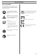
Key to symbols Key to symbols The symbols below are used on the machine and in this Operator’s Manual. It is important that the user understands the significance of these in order to work with the machine safely. Please read the operator’s manual carefully and make sure you understand the instructions before using the machine. WARNING! Dust forms when grinding which can cause injuries if inhaled. Use an approved breathing mask. Always provide for good ventilation.
Safety Instructions Safety Instructions • Never use the machine if you are tired, if you have drunk alcohol, or if you are taking medication that could affect your vision, your judgement or your coordination. • Never use a machine that has been modified in any way from its original specification. • Be on your guard for electrical shocks. Avoid having body contact with lightning-conductors/metal in the ground.
Introduction Introduction IMPORTANT! The Husqvarna PG 680/820 floor surfacing machines are designed for wet or dry grinding of marble, terrazzo, granite and concrete. Their applications range from rough grinding through to a polished finish. This manual covers the Husqvarna PG 680/820 series of floor grinders equipped with twin motor drive here after referred to as Dual Drive Technology™.
What is what 1. 11. 2. 3. 10. 4. 5. 9. 6. 7. 8. What is what 1. Hour counter 8. Chassis/Frame 2. Electrical cabinet 9. Handle bars 3. Planetary head motor 1.5kW/1Hp 10. Control Panel 4. Grinding/Satellite heads motor 11kW/15Hp 11. Handle bar adjuster 5. Lifting lugs 6. Cover/Shroud 7.
What is what The machine can be divided into two main parts. These can be identified as follows: IMPORTANT! 1. Chassis/Frame section – comprising handle bars, Planetary head and grinding heads are set to both turn in the same direction (i.e. both in clockwise rotation or both in counter-clockwise rotation). electrical cabinet, steel frame and wheels. 2. Head – comprising of motors, cover, grinding/satellite/ planetary heads and internal components.
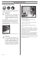
Setting up/Operation Setting up/Operation Position grinder on the working area. Make sure there are diamonds underneath machine and that the head locks/shear pins are tight. IMPORTANT! When using the machine, each grinding head must always have the same diamond type and number of diamonds as the other grinding heads. Each grinding head must have diamonds the same height as the other grinding heads.
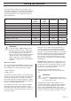
Setting up/Operation Speed and direction setting is often a matter of personal choice. Operators are encouraged to experiment to find which settings best suit the given applications. The following table lists some suggested set-ups for different applications.
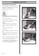
Changing the diamonds Changing the diamonds As different applications require different selections of diamond tools, there will be many occasions when the grinding discs need to be changed. Following is a guide for this procedure. Preparation 1. Ensure STOP/RUN switch is in STOP position as unintentional starting of machine while changing discs can result in serious injury. 2. Have a set of gloves ready, as diamonds can get very hot during dry grinding applications. Changing 1.
Variable speed drives/frequency converters Variable speed drives/ frequency converters Each Husqvarna PG 680 & 820 is equipped with 2 variable speed drive or frequency converter. This unit is incorporated into the machine for the following reasons: 1. Functional • Manipulate incoming power to enable increase/ decrease in speed & direction change. • Regulate current and voltage supply to the motors to ensure motors run at optimum levels (e.g. torque boost). 1. 8. 2.
Variable speed drives/frequency converters Monitor screen Information provided OUTPUT FREQUENCY Frequency motor is running at when machine is running. REF. FREQUENCY Frequency speed control dial is set to. MOTOR SPEED Speed of motor when machine is running. MOTOR CURRENT Current draw of motor when machine is running. MOTOR TORQUE Percentage of motor torque when machine is running. MOTOR POWER Percentage of motor power when machine is running.
Variable speed drives/frequency converters Menus and information they provide The following menu items/screens on the variable speed drive/frequency converters provide the following useful information to the operator. OUTPUT FREQUENCY (Monitor Menu) This screen tells the operator the frequency the motor is running at when the machine is in operation. The value for output frequency should be constant when the machine is running.
Faults and trouble shooting Faults and trouble shooting When either one of the variable speed drives or frequency converters in the machine experience a fault and “trip” out, they will cease to run and an error message will appear flashing on the keypad display (see picture below). The following list are the most commonly experienced faults and possible action steps. Fault code Fault Code Possible Cause Action 1—OVERCURRENT Motor being worked too hard and drawing extra current.
Faults and trouble shooting Further problems that may be experienced when using the grinder and potential solutions are as follows: Problem Possible Cause Potential Solution GRINDER IS HARD TO HOLD ONTO Not enough diamonds under the machine (if grinding thick glue or soft floors, too few diamonds under the machine will greatly increase the load on grinder and operator). Usually also accompanied by high current draw by large motor.
Diamonds Diamonds Background Diamond abrasives usually consist of 2 components: 1. Diamond powder (also known as diamond crystals or grit). By changing the size of the diamond powder or grit, we can change how coarse or fine the scratches will be that are left behind from the grinding process. 2. A binding agent (metal or resin). Diamond powder is mixed and suspended in either a metal or resin binding agent.
Diamond selection Diamond Holder Disc Full set of single segments Half set of single segments Position for Diamond segment Full set of twin segments Half set of twin segments Diamond selection Generally speaking, the faster a diamond segment wears, the faster the productivity will be. By varying the above factors, changes can also be made to effect the following: • Scratch pattern. • Current draw of machine. • Flatness of floor (see next section). • Ease of operation.
Diamond selection Full and half sets of diamonds By changing the way the diamonds are set-up on the diamond holder discs, an operator can significantly effect the performance of the machine and therefore, the finished product. HALF-SET OF DIAMONDS When the diamonds are set-up as a half-set, they tend to follow the surface of the floor. Similar to a tripod for a camera, which can be placed on an uneven surface and yet still find a stable footing.
Diamond selection Selecting the correct diamonds for your application The following suggestions cover the basic principles for diamond selection for different applications.
Diamond selection Determining the hardness of concrete All concrete may feel hard (particularly if you fall over on it), so what do we mean when we talk about hard, medium and soft concrete? All concretes are measured by their compressive strength and depending on which part of the world you are from, different compressive strength indices (e.g. PSi & MPa). Generally speaking, the higher the compressive strength rating, the harder the concrete and therefore, the harder it will be to grind.
Maintenance Maintenance Used correctly, the machine is an extremely low-maintenance and reliable. The head pins are fixed to the head plate giving rigidity and stability. The head mate is situated above the head plate and is held in place by a series of holes – head pin holes. 1. 1. 2. 2. This section covers the general maintenance items that need attention on a periodic basis. There are three main mechanical items to check: 1. Grinding Heads. 2. Planetary drive system. 3. Planetary seal. 1.
Maintenance Spring Steel Heads The below diagrams illustrate the main parts comprising this type of grinding head. Unlike with the conventional/demolition heads, the spring steel heads are able to move in a flexible manner without any moving parts due to the presence of the spring steel spring. Diagram 1 1. Spring steel spring 2. Head plate Over an extended period of time the spring steel spring fatigues and the spring steel “fingers” begin to break off.
Maintenance Grinding Heads Drive System IMOPRTANT! The grinder comes equipped with Dual Drive Technology™. As the grinding discs are driven by the large motor via an internal belt, and because the belt is sealed inside the machine, there is no maintenance regarding this drive system until a major service (belt and bearing replacement) is due. This is typically following 12-36 months of operation.
Maintenance The effectiveness of the planetary seal can be monitored by the simple removal of the planetary motor / gearbox system by removing the four bolts shown below. Remove 2 bolts either side. Remove 2 bolts either side. Remove this bolt. Remove cover off motor terminal box. Inspect for dust build up here Remove these bolts. If the planetary seal is working effectively, there should be a very minimal amount of dust observed under the cover of the machine.
Maintenance schedule Maintenance schedule Item Action Frequency Check that head locks are tight. Tighten head locks and re-set in thread-locking compound if required (Suggested thread-locking compound Loctite 680) Daily Inspect heads for slop/ Examine machine heads while machine tipped back. broken “fingers” if using Disconnect Planetary Drive motor (small motor) and run spring steel heads. discs at lowest speed. Check to see how concentric/true grinding heads are running.
Technical Data Technical Data PG 820 PG 680 Grinding width 820mm (32") 680mm (27") Grinding disc 3x270mm (10.5") 3x240mm (9.5") Weight 440kg (970lbs) 385kg (850lbs) Grinding pressure total 335kg (737lbs) 300kg (660lbs) Grinding pressure per disc 112kg (246lbs) 100kg (220lbs) Motor Power 3-Phase 380-480V 12.5kW(17.0hp) 3-Phase 380-480V Power per grinding disc 4.15kW (5.7hp) 4.15kW(5.
Technical Data EC-declaration of conformity (Applies to Europe only) Husqvarna Construction Products, SE-433 81 Göteborg, Sweden, tel: +46-31-949000, declares under sole responsibility that the Husqvarna PG680/PG820 dating from 2007 serial numbers and onwards (the year is clearly stated on the rating plate, followed by the serial number), complies with the requirements of the COUNCILíS DIRECTIVE: - of June 22, 1998 ”relating to machinery” 98/37/EC, annex IIA.
www.husqvarnacp.