RIDE R 85 0 RID RIDE ER 850 R 97 0 Rider 850/970 Operator´s manual Please read these instructions carefully and make sure you understand them before using the machine. 101 89 35-26 101 89 35-26 Eng 1 97-10-14, 14.
TOM 1 97-10-14, 14.
E CONTENTS Operator’s Manual for Rider 850 Rider 970 Safety instructions ............................................. 2 Safety rules, USA nomenclature ....................... 2 Explanation of symbols ..................................... 4 Safety instructions ............................................. 5 General use ........................................................ 5 Driving on slopes ................................................6 Children .....................................................
E SAFETY INSTRUCTIONS ! 1. Safety rules, USA nomenclature ! Safe operation practices for ride-on mowers IMPORTANT! This cutting machine is capable of amputating hands and feet and throwing objects. Failure to observe the following safety instructions could result in serious injury or death. I. General operation 1. Read, understand and follow all instructions in the manual and on the machine before starting. 2.
SAFETY INSTRUCTIONS IV. Service E Wheel assembly (USA) 1. Use extra care in handling gasoline and other fuels. They are flammable and vapours are explosive. a) Use only an approved container. b) Never remove gas cap or add fuel with the engine running. Allow engine to cool before refuelling. Do not smoke. c) Never refuel the machine indoors. d) Never store the machine or fuel container inside where there is an open flame, such as in a water heater. 2. Never run a machine inside a closed area. 3.
E EXPLANATION OF SYMBOLS These symbols are on the machine and in the operator´s manual. Study them carefully so that you know what they mean. Read the operator´s manual.
E SAFETY INSTRUCTIONS These instructions are for your safety. Read them carefully. ! This symbol implies that important safety rules are applicable. This is for your safety and the operating reliability of the machine. General use: • Make yourself familiar with the controls and how to stop quickly. • Read all the instructions in Operator’s Manual and on the machine before starting it. Make sure you understand them, and then follow them.
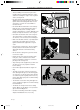
E SAFETY INSTRUCTIONS • Watch out for traffic when working close to a road, or crossing one. • Be careful when rounding a fixed object so that the blades do not hit it. Never drive intentionally over a foreign object. • The machine is heavy and can cause very severe crush injuries. Be extra careful when loading it on a trailer or truck. • Be careful when pulling a load or using heavy equipment. a. Only use approved tow hooks. b. Limit the load to what you can manage safely. c.
E SAFETY INSTRUCTIONS • Do not cut close to edges, ditches or banks. The machine can suddenly tip over if a wheel goes over the edge of a drop or a ditch, or if a bank gives way. • Do not cut wet grass. It is slippery and the tyres can loose their grip so that the machine slides. • Do not try to stabilise the machine by placing one foot on the ground. Children Tragic accidents can occur if the driver does not pay attention to children in the vicinity.
E SAFETY INSTRUCTIONS • Avoid overfilling. If fuel has been spilt on the machine wipe it up and wait until it has evaporated before starting the engine. If fuel is spilt on clothes, change them. • Be extra careful when handling battery acid. Spilling acid on the skin can cause severe burn injuries. Rinse immediately with water. If acid gets into the eyes this can cause blindness. Contact a doctor. • Be careful with the maintenance of the battery. Explosive gas is formed in the battery.
E PRESENTATION Presentation The machines have gearboxes of the in-line type, with 5 forward gears and one reverse gear, which enables selection of the best speed for mowing and transport. These instructions describe two machine models, Rider 850 and Rider 970. Both models are fitted with engines from Briggs & Stratton of 10.5, 12.5 and 15.5 hp.
E PRESENTATION Throttle and Choke lever The engine speed is adjusted with the throttle control, and thereby also the rotation speed of the blades. The control is also used to activate the choke function. When the choke is used the engine receives a richer mixture of fuel and air, which simplifies cold start. Clutch pedal The clutch pedal disengages the engine and stops forward movement. The blades are not affected by the clutch pedal.
E PRESENTATION Parking brake The parking brake consists of a catch which enables the brake to be locked in braking position. Gear shift The gearbox is of the in-line type, which implies that gear shifting can be made directly from neutral to fifth gear without stopping in each gear. The gearbox has five forward gears, neutral, and reverse. When engaging reverse gear the lock button on the gear shift must be pressed. Cutting unit Rider 850 has a cutting unit with rear ejection, i.e.
E PRESENTATION Lift lever for cutting unit The lift lever is used to set the cutting unit in transport or cutting position. If the lever is pulled back the unit will lift up and the blades stop rotating (transport position). If the lock button is pressed and the lever is moved forward the unit will lower down and the blades begin rotating (cutting position). The lever can also be used to temporarily regulate the cutting height, e.g. for a small mound in the lawn.
E PRESENTATION Seat The seat has a jointed attachment on the front edge and can be tipped forward. The seat can also be adjusted lengthways. Release the wheels under the seat and adjust it forwards or backwards to the required position. Lock the adjustment with the wheels. Fuelling The engine should be run on at least 92 octane leaded or unleaded petrol/gasoline (not oil mixed). For USA and Canada at least 87 octane leaded or unleaded petrol/gasoline (not oil mixed).
E DRIVING Before starting • Read the safety instructions and information on the location and function of the controls before starting (see pages 5–13). • Conduct daily maintenance before starting (see maintenance schedule on page 19). Adjust the seat to the required position. Starting the engine 1. Lift up the cutting unit by pulling the lever backwards to locked position (transport position). 2. Apply the parking brake. This is done as follows: 2 • Press down the brake pedal (1).
E DRIVING Cold engine: 4. Push the throttle control to position 3 (choke position). In this position the engine receives a richer mixture so that the engine starts more easily. 2 1 3 Warm engine: 5. Set the throttle control midway between position 1 and 2. 2 1 3 6. Turn the ignition key to start position. IMPORTANT INFORMATION STOP START Do not run the starter for more than about 5 seconds at a time. If the engine does not start, wait about 10 seconds before trying again. 7.
E DRIVING Driving the machine 1. Release the parking brake by pressing the brake pedal. 2. Press the clutch and engage the required gear. The gearbox has five forward drive positions, neutral, and reverse. To engage reverse gear the lock button must be pressed down. • Gears 1–4 are used for mowing. • Gears 4–5 are used for transport. Starting is possible irrespective of which gear is engaged. Carefully release the clutch pedal and drive to the mowing area.
E DRIVING 3. Select the required cutting height (1–9) with the cutting height lever. To obtain a uniform cutting height it is important that the tyre pressures are equal on both front wheels (60 kPa). 4. Push in the lock button on the lift lever and lower down the cutting unit. IMPORTANT INFORMATION The service-life of the drive belts increases considerably if the engine is run at low speed when engaging the blades.
E DRIVING Starting on slopes 1. Apply the parking brake. 2. Push the throttle control to 3/4 position to full throttle position. 3. Push down the clutch and engage first gear. 4. Carefully release the clutch. 5. When the engine begins to drive, release the parking brake. ! MAX 15° WARNING! Never drive the machine on ground with a slope of more than 15°. Mow slopes upwards and downwards, never across. Avoid sudden changes in direction.
E MAINTENANCE Maintenance schedule The following is a list of the maintenance which should be conducted on the machine. For the items which are not described in these instructions go to an authorised service workshop.
E MAINTENANCE Dismantling of the machine hoods Engine hood The engine is accessible for servicing when the engine hood is lifted up. Tilt the seat forward, release the rubber strap under the seat, and tilt the hood backwards. Front hood Release the screws in the front hood (3) and lift off the hood. RID Right-hand fender Release the screws in the fender (2) and lift off the fender. Left-hand fender Release the screws in the fender (2) and lift off the fender.
E MAINTENANCE Check the engine’s oil level Check the oil level in the engine when the machine is horizontal. Dismantle the engine hood as per the description on page 20. Release the dip stick and pull out. Wipe off the oil and insert again. The dip stick must be fully screwed down. Now release the dip stick again and pull out. Check the oil level. The oil level should lie between the markings on the dip stick. If the level approaches the ADD mark, top up with oil to the FULL mark.
E MAINTENANCE Checking and adjustment of the steering wires The steering is controlled by means of wires. These can in time become slack, which implies that the adjustment of the steering becomes altered. Check and adjust the steering as follows: 1. Dismantle the frame-plate by releasing the screws (two on each side). 2. Check the tension of the steering wires by pushing them together as shown in the diagram.
E MAINTENANCE Checking the brake The brake is of the disc brake type and is fitted on the gearbox. Check that the brake is correctly adjusted by measuring the distance between the brake lever and the front edge of the recess on the chassis. The distance should be 0–1 mm when the brake is not applied. Adjusting the brake 1. Release the lock nuts (1). 2. Tension the wire with the adjusting screw (2) so that the distance between the brake lever and the front edge of the recess on the chassis is 1 mm. 3.
E MAINTENANCE Replacing the air filter If the engine seems to lack power or goes irregularly the reason may be that the air filter is clogged. It is therefore important to replace the air filter at regular intervals (see maintenance schedule on page 19 for correct service interval). The air filter is replaced as follows: 1. Dismantle the engine hood as described on page 20. 2. Remove the air filter housing’s plastic cover by releasing the wing-nut. 3.
E MAINTENANCE Checking and adjustment of the cutting unit’s ground pressure Rider 970 To achieve the best cutting results the cutting unit should follow the underlying surface without pressing too hard against it. The pressure is adjusted with a screw on each side of the machine. Adjusting of the cutting unit’s ground pressure is conducted as follows: 1. Place a set of bathroom scales under the cutting unit’s frame (front edge) so that it rests on the scales.
E MAINTENANCE Adjustment of the cutting unit’s parallelism Adjustment of Rider 850 1. Dismantle the front hood and right-hand fender as described on page 20. 2. Vertical adjustment of the cutting unit is made with the adjusting nuts on the back edge of the lift-strut. 2 3. Raise the cutting unit at the front edge by shortening the lift-strut. Lower the cutting unit at the front edge by lengthening the lift-strut. 4. Tighten the nuts against each other after the adjustment. 5.
E MAINTENANCE Dismantling the cutting unit The cutting unit can be released from the machine for cleaning or checking of the blades and screws. 1 Dismantle the cutting unit on Rider 850 as follows: 1. Dismantle the front hood and right-hand and lefthand fenders as described on page 20. 2 2. Raise the cutting unit by pulling the lift lever backwards to the transport position. 3. Dismantle the drive belt (1). 4.
E MAINTENANCE Checking the blades To achieve the best mowing results it is important that the blades are undamaged and well-sharpened. Check that the blades’ attachment screws are tight. IMPORTANT INFORMATION IMPORTANT INFORMATION On the Bioclip unit the relative positioning of the blades should always be as shown in the diagram with an angle of 90° between the blades. Otherwise the blades can go against each other and damage the unit.
E MAINTENANCE Changing the oil The oil should be changed for the first time after 5 hours of running time. Thereafter it should be changed every 25 hours of running time. ! WARNING! Engine oil can be very hot if it is drained off directly after the engine is stopped. Therefore allow the engine to cool down first. 1. Place a receptacle under the engine’s drain plug, located on the left-hand side of the engine. 2. Remove the dip stick and drain plug. 3. Let the oil run out into the receptacle. ADD 4.
E MAINTENANCE Checking and adjustment of the throttle wire If the engine does not respond as it should do when the throttle lever is moved or if the top speed is not reached, the throttle wire may need adjusting. 1. Release the clamping screw (see arrow) and push the throttle control to full throttle position. 2. Pull the throttle wire’s outer casing to the far right and tighten the clamping screw.
E TROUBLE SHOOTING SCHEDULE Problem Procedure Engine will not start. • • • • Fuel tank empty. Plug defective. Plug connection defective. Dirt in carburettor or fuel pipe. Starter does not pull round engine. • • • • • • Battery flat. Bad contact between cable and battery terminal. Lift lever for cutting unit in wrong position. Main fuse blown. Ignition lock faulty. Gear shift/hydrostat pedal not in neutral. Engine does not run smoothly. • • • • • • • Wrong gear, too high. Plug defective.
E STORAGE Winter storage At the end of the season the machine should immediately be put in order for storage, also if it is going to stand idle for more than 30 days. Fuel which is left to stand for long periods (30 days or more) can leave tacky deposits which can block the carburettor and interfere with the engine. Fuel stabiliser is an acceptable alternative to avoid tacky deposits during storage. If alkylate petrol (Aspen) is used stabiliser is not necessary since this fuel is stable.
E TECHNICAL DATA Dimensions Rider 850 Rider 970 Length Width 2000 mm 960 mm Height Unladen weight Wheel base Track Tyre size Tyre pressure, front & rear Max. gradient 1060 mm 225 kg 820 mm 610 mm 16 x 6.50 x 8 60 kPa (0.6 kp/cm2) 15° 2145 mm 1050 mm (970-15.5), 1260 mm (970-15.5S) 1120 (970-Bioclip) 1060 mm 240 kg 855 mm Front 715 mm, rear 610 mm 16 x 6.50 x 8 60 kPa (0.6 kp/cm2) 15° Engine Manufacture Briggs & Stratton model 28B707 type 0139, trim 01 (850-10.
´*2}T¶6B¨