Operator’s Manual ST 151 Gasoline containing up to 10% ethanol (E10) is acceptable for use in this machine. The use of any gasoline exceeding 10% ethanol (E10) will void the product warranty. 115 68 51-27 Please read the owner's manual carefully and make sure you understand the instructions before using the machine.
CONGRATULATIONS on your purchase of a new snow thrower. It has been designed, engineered and manufactured to give best possible dependability and performance. Should you experience any problem you cannot easily remedy, please contact your nearest authorized service center. We have competent, well-trained technicians and the proper tools to service or repair this unit. Please read and retain this manual. The instructions will enable you to assemble and maintain your snow thrower properly.
Operation Maintenance and Storage 1. Do not put hands or feet near or under rotating parts. Keep clear of the discharge opening at all times. 2. Exercise extreme caution when operating on or crossing gravel drives, walks, or roads. Stay alert for hidden hazards or traffic. 3. After striking a foreign object, stop the engine (motor), disconnect the cord on electric motors, thoroughly inspect the snow thrower for any damage, and repair the damage before restarting and operating the snow thrower. Remove key.
TABLE OF CONTENTS SAFETY RULES ........................................................ 2-3 PRODUCT SPECIFICATIONS ...................................... 3 CUSTOMER RESPONSIBILITIES................................ 3 SAFETY AND INSTRUCTIONAL DECALS ................. 4 ASSEMBLY ................................................................ 5-6 PRODUCT OVERVIEW ................................................ 7 OPERATION ............................................................ 8-11 MAINTENANCE .........
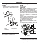
ASSEMBLY Setup 4. Pull up and push down slightly on the handle to verify handle is locked into place (Figure 4). NOTE: If handle feels unsecure with the adjustment levers closed, tighten adjustment handle nuts until the handle feels secure. 5. Remove the cardboard from recoil start handle and feed the recoil rope through the rope guide. Loose Parts Use the chart below to verify that all parts have been shipped. Description Qty.
ASSEMBLY Installing the Discharge Chute Filling the Engine with Oil Procedure ENGINE 1. Install the chute deflector to the discharge chute using bolts and, washer, nut, deflector knob and cap plunger (Figure 6). See engine manual. LUBRICATION NOTE: SAE 10W30 or SAE 5W30 oil is acceptable for use in cold temperatures if engine is difficult to start. 2. Install the discharge chute to the chute base using three screws and nuts. NOTE: Although multi-viscosity oils (5W30, 10W30 etc.
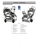
PRODUCT OVERVIEW Product Overview 10 2 12 1 16 17 3 9 11 4 13 8 *7 *7 6 14 15 5 Figure 8 1. 2. 3. 4. 5. Discharge chute Chute deflector Fuel tank cap Primer Electric-start button (if equipped) 6. Oil drain plug 7. Oil fill cap/dipstick 8. Choke lever 9. 10. 11. 12. 13. 14. 15. 16. 17. Ignition key Chute rotator handle Recoil start handle Control bar Lights Drive side cover Auger blade Deflector knob Owner's Manual * Dipstick location may vary depending on engine type.
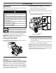
OPERATION Operation Checking the Engine Oil Level NOTE: Determine the left and right sides of the machine from the normal operating position. 1. Move the snowthrower to a level surface. 2. Clean around the dipstick (Figure 10). NOTE: Dipstick location may vary depending on engine type. • Gasoline is extremely flammable and explosive. A fire or explosion from gasoline can burn you and others.
OPERATION Starting the Engine 1. Push key in (Figure 11). 2. Move choke lever to left position. 3. Firmly push in the primer 2 times with your thumb, holding the primer in a for a second before releasing it each time. NOTE: Remove your glove when you push in the primer so that air cannot escape from the primer hole. 1 IMPORTANT: It may not be necessary to use the primer or the choke if the engine has been running and is hot. Excessive priming may flood the engine and prevent it from starting.
OPERATION Engaging the Auger Blades 1. To engage the auger blades, hold the control bar against the handle (Figure 14). 1 1 2 Figure 16 1. Rub Area 2. Wear Areas Stopping the Engine Figure 14 1. To stop the engine, pull key out (Figure 17). 1. Control bar 1 Disengaging the Auger Blades 1. To disengage the auger blades, release the control bar (Figure 15). 1 Figure 17 1. Key Adjusting the Discharge Chute and Chute Deflector Figure 15 1. Control bar 1.
OPERATION Preventing Freeze-up After Use 2. To raise or lower the angle of the chute deflector, loosen both chute deflector knobs on the chute deflector and move the chute deflector up or down to desired position and retighten knobs (Figure 19). • Let the engine run for a few minutes to prevent moving parts from freezing. Stop the engine, wait for all moving parts to stop, and remove ice and snow from the snowthrower. • Clean off any snow and ice from the base of the chute.
MAINTENANCE Maintenance NOTE: Determine the left and right sides of the machine from the normal operating position.
MAINTENANCE Inspecting the Auger Blades/ Scraper Bar 5. After draining the used oil, return the snowthrower to the operating position. 6. Install the oil drain plug and torque to 145-150 in-lbs (17 N-m). Before each session, inspect the auger blades for wear. When an auger blade edge or the scraper bar has worn down have an Authorized Service Dealer replace the auger blades and the scraper bar (Figure 23). NOTE: Dipstick location may vary depending on engine type. 7.
MAINTENANCE Servicing the Spark Plug 8. Unsnap top cover by firmly pulling upwards at the rear section of the cover disengaging the three clips (Figure 29). 9. Shift top cover until fuel tank is clear of the rear upper cover and set top cover to the side of the unit. 10. Temporarily reinstall oil fill cap to prevent foreign object from entering the engine. 11. Remove 2 screws in the side cover and rear covers on both sides. Use a NGK BPR6ES, Champion RN9YC, or BOSCH WR6DC spark plug or equivalent. 1. 2.
MAINTENANCE 19. Install the spark plug and torque it to 20–22 ft-lb (27–30 N-m). 20. Connect the spark plug wire to the spark plug (Figure 31). 21. Reattach primer bulb tube to primer bulb and electrical wires on back ignition switch of rear upper cover (Figure 30). 22. Set rear upper cover in place so the two screw holes line up with the rear lower cover and side covers (Figure 33). 15. Disconnect the spark plug wire from the spark plug (Figure 31). 16. Clean around the spark plug. 17.
MAINTENANCE Replacing the Drive Belt 4. Install the new auger v-belt and drive pulley, routing it as shown in Figure 35. NOTE: Route the new auger v-belt first around the engine pulley, then the idler pulley, and finally around the drive pulley while pressing down on the front of the idler arm. (Figure 35). If auger v-belt becomes worn, oil-soaked, excessively cracked, frayed, or otherwise damaged, replace the belt. 1. Remove the drive side cover by removing the six screws as shown in (Figure 34). 4 5.
STORAGE Storage ENGINE OIL Drain oil (with engine warm) and replace with clean engine oil. (See “Changing the Engine Oil” section of this manual). STORING THE SNOWTHROWER Immediately prepare your snow thrower for storage at the end of the season or if the unit will not be used for 30 days or more. CYLINDER 1. Remove spark plug. 2. Pour one ounce (29 ml) of oil through spark plug hole into cylinder. 3. Pull recoil starter handle slowly a few times to distribute oil.
TROUBLESHOOTING Troubleshooting See appropriate section in manual unless directed to a service center/department. PROBLEM CAUSE CORRECTION Does not start 1. Safety ignition key is not inserted. 1. Insert safety ignition key. 2. Out of fuel. 2. Fill fuel tank with fresh, clean gasoline. 3. ON/OFF switch is OFF. 3. Move ON/OFF switch to ON position. 4. Choke in OFF position. 4. Move to FULL position. 5. Primer not depressed. 5. Prime as instructed in the Operation section of this manual.
SERVICE NOTES 19
Consumer Wheeled Products - Limited Warranty Husqvarna warrants to the original retail purchaser that this Husqvarna® product is free from defects in material or workmanship under normal use and maintenance from the date of retail purchase for the applicable Warranty Period shown on Exhibit A. This Limited Warranty may not be transferred to any subsequent purchaser of this Husqvarna® product. Certain components (e.g.
(a) Abrasion to mower decks; (b) Tires damaged by external punctures; (c) Natural discoloration of materials due to ultraviolet light; (d) Damage to cutting equipment by way of contact with, rocks, or other non-approved materials and/or structures; In addition, this Limited Warranty does not cover damages, malfunctions or failures resulting from abuse or neglect of the product related to or including any of the following: (e) Failure to provide or perform required maintenance services as prescribed
Consumer Wheeled Limited Warranty Chart 2013 Product/Component Riding Lawn Tractors: Frame, Chassis, Front Axle Engine* Transmission (if made by Husqvarna/Peerless) Transmission (if third party)** XLS Models only - stamped deck shell.
Consumer Wheeled Limited Warranty Chart 2013 Consumer (personal, household use only) Commercial (any commercial, professional, institutional, agricultural, or income producing use, other than Rental Use) 1 Year 90 days No Warranty No W arranty Product/Component Parts & Accessories (if purchased) Accessories (e.g., grass catcher, bumper guard accessories, etc. Parts (e.g., belts, blades, etc.
07/09/2014 TH/AP