Operator’s Manual ST 230P Gasoline containing up to 10% ethanol (E10) is acceptable for use in this machine. The use of any gasoline exceeding 10% ethanol (E10) will void the product warranty. 115 73 42-27 Rev. 5 Please read the owner's manual carefully and make sure you understand the instructions before using the machine.
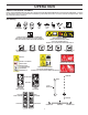
IMPORTANT Safe Operation Practices for Walk-Behind Snow Throwers This snow thrower is capable of amputating hands and feet and throwing objects. Failure to observe the following safety instructions could result in serious injury. WARNING: Snow throwers have exposed rotating parts, which can cause severe injury from contact, or from material thrown from the discharge chute. Keep the area of operation clear of all persons, small children and pets at all times including startup.
6. When cleaning, repairing or inspecting the snow thrower, stop the engine and make certain the collector/ impeller and all moving parts have stopped. Disconnect the spark plug wire and keep the wire away from the plug to prevent someone from accidentally starting the engine. 7. Do not run the engine indoors, except when starting the engine and for transporting the snow thrower in or out of the building. Open the outside doors; exhaust fumes are dangerous. 8.
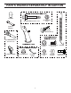
PARTS PACKED SEPARATELY IN CARTON (3) KNOB (6) SHEAR BOLTS 1/4-20 x 1-3/4 (6) LOCKNUTS 1/4-20 (1) MULTIWRENCH SAFTEY IGNITION KEY (S) (2) CARRIAGE BOLTS 5/16-18 x 2 1/4” (1) LOCKNUT 5/16-18 (2) HANDLE KNOBS (1) LOCKNUT 3/8 (1) CABLE GUIDE 4 (1) LOCKNUT 1/4-20 (1) CARRIAGE BOLT 5/16-18 x 5/8 (1) NYLON WASHER (1) SPRING (1) SHOULDER BOLT 1/4-20
ASSEMBLY / PRE-OPERATION Read these instructions and this manual in its entirety before you attempt to assemble or operate your new snow thrower. Reading the entire manual will familiarize you with the unit, which will assist you in assembly, operation and maintenance of the product. Your new snow thrower has been assembled at the factory with the exception of those parts left unassembled for shipping purposes. All parts such as nuts, washers, bolts, etc.
ASSEMBLY / PRE-OPERATION INSTALL DISCHARGE CHUTE / CHUTE ROTATOR HEAD (See Fig. 4 and 5) NOTE: The multi-wrench provided in your parts bag may be used to install the chute rotator head. 1. Place discharge chute assembly on top of chute base with discharge opening toward front of snow thrower. 2. Position chute rotator head over chute bracket. If necessary, rotate chute assembly to align square and pin on underside of chute rotator head with holes in chute bracket. 3.
OPERATION KNOW YOUR SNOW THROWER READ THIS OWNER'S MANUAL AND ALL SAFETY RULES BEFORE OPERATING YOUR SNOW THROWER. Compare the illustrations with your snow thrower to familiarize yourself with the location of various controls and adjustments. Save this manual for future reference. These symbols may appear on your snow thrower or in literature supplied with the product. Learn and understand their meaning.
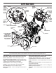
OPERATION CHOKE CONTROL MUFFLER THROTTLE / ENGINE CONTROL ON / OFF SWITCH AUGER CONTROL LEVER POWER CORD PLUG GASOLINE FILLER CAP ELECTRIC START BUTTON DISCHARGE CHUTE CONTROL LEVER DRIVE SPEED CONTROL LEVER DEFLECTOR REMOTE CONTROL LEVER LIGHT TRACTION DRIVE CONTROL LEVER LH TURN TRIGGER PRIMER SAFETY IGNITION KEY FUEL SHUT-OFF VALVE RECOIL STARTER HANDLE CHUTE DEFLECTOR CLEAN-OUT TOOL DISCHARGE CHUTE HANDLE KNOB NOTE: ITEMS ABOVE ARE SHOWN IN THEIR TYPICAL LOCATION ON THE ENGINE.
OPERATION The operation of any snow thrower can result in foreign objects thrown into the eyes, which can result in severe eye damage. Always wear safety glasses or eye shields while operating your snow thrower or performing any adjustments or repairs. We recommend standard safety glasses or a wide vision safety mask worn over spectacles. TO USE THROTTLE CONTROL (See Fig. 11) The throttle control is located on the engine. Always operate the snow thrower with the engine at full throttle.
OPERATION • Squeeze traction drive control lever to handle to engage the drive system. • Release traction drive control lever to stop the forward or reverse movement of the snow thrower. SPEED and DIRECTION are controlled by the drive speed control lever. • Push right on the speed control lever and move lever to desired position BEFORE engaging the traction drive control lever. Be sure lever springs back and locks into desired position. TO THROW SNOW (See Fig.
OPERATION BEFORE STARTING THE ENGINE TO ADJUST SKID PLATES (See Fig. 17) NOTE: The wrench provided in your parts bag may be used to adjust the skid plates. Skid plates are located on each side of the auger housing and adjust the clearance between the scraper bar and the ground surface. Adjust skid plates evenly to proper height for current surface conditions.
OPERATION TO START ENGINE • Ensure fuel shut-off valve is in the “OPEN” position. Your snow thrower engine is equipped with both a 120 Volt A.C. electric starter and a recoil starter. The electric starter is equipped with a three-wire power plug and is designed to operate on 120 Volt A.C. household current. • Ensure your house is a 120 Volt A.C. three-wire grounded system. If you are uncertain, consult a licensed electrician.
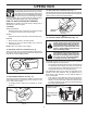
MAINTENANCE LUBRICATION CHART GENERAL RECOMMENDATIONS ➀ ➁ ➂ The warranty on this snow thrower does not cover items that have been subjected to operator abuse or negligence. To receive full value from the warranty, operator must maintain snow thrower as instructed in this manual. Some adjustments will need to be made periodically to properly maintain your snow thrower. All adjustments in the Service and Adjustments section of this manual should be checked at least once each season.
MAINTENANCE Check the crankcase oil level before starting the engine and after each five (5) hours of continuous use. Tighten oil fill cap / dipstick securely each time you check the oil level. TO CHANGE ENGINE OIL Determine temperature range anticipated before next oil change. All oil must meet API service classification SJ–SN. • Be sure snow thrower is on level surface. • Oil will drain more freely when warm. • Catch oil in a suitable container.
SERVICE AND ADJUSTMENTS To replace the shear bolts: 1. Disengage all controls and move throttle control to STOP position. Wait for all moving parts to stop. 2. Remove safety ignition key and disconnect spark plug wire from spark plug. Place wire where it cannot come in contact with spark plug. 3. Align holes in impeller hub with holes in impeller shaft and install two (2) new 2" shear bolts. Install 1/4-20 locknuts and tighten securely.
SERVICE AND ADJUSTMENTS TO REPLACE BELTS AUGER BELT REPLACEMENT (See Fig. 22) TO REMOVE AUGER BELT 1. Remove upper 5/16" bolts and lower 1/4" bolts from both sides of the frame assembly. Do not discard bolts. 2. Loosen but DO NOT REMOVE lower 5/16" bolts on both sides of the frame assembly. 3. Remove the auger belt from the engine pulley. 4. Tip the back section down. The front section will tip forward at the same time, as the bottom bolt acts as a hinge between the front and back sections.
SERVICE AND ADJUSTMENTS AFTER REPLACING BELT(S) 1. INSTALL BELT COVER and two (2) screws. Tighten securely. 2. INSTALL DISCHARGE CHUTE – See “INSTALL DISCHARGE CHUTE / CHUTE ROTATER HEAD” in the Assembly section of this manual. DRIVE BELT REPLACEMENT (See Fig. 23) TO REMOVE DRIVE BELT 1. Remove auger belt. See “TO REMOVE AUGER BELT” in this section. 2. Remove tensioner spring attached to drive belt tensioner arm. 3. Remove return spring holding the swing plate in place. 4.
SERVICE AND ADJUSTMENTS TO ADJUST CHUTE ROTATOR CABLE TENSION (See Fig. 25) 1. Adjust cable tension by loosening the jam nuts next to the turn buckle. 2. Grasp the short section and hold while turning the long section to lengthen the adjuster. 3. Adjust until cable is snug and tighten jam nuts. ADJUSTER TURN BUCKLE AUGER PERFORMANCE AND CABLE ADJUSTMENT (See Fig. 25) NOTE: If you do not feel comfortable making this adjustment yourself, please contact an authorized service center/ department.
STORAGE Immediately prepare your snow thrower for storage at the end of the season or if the unit will not be used for 30 days or more. • Empty the fuel tank by starting the engine and letting it run until the fuel lines and carburetor are empty. • Never use engine or carburetor cleaner products in the fuel tank or permanent damage may occur. • Use fresh fuel next season. NOTE: Fuel stabilizer is an acceptable alternative in minimizing the formation of fuel gum deposits during storage.
TROUBLESHOOTING See appropriate section in manual unless directed to a service center/department. PROBLEM CAUSE CORRECTION Does not start 1. Fuel shut-off valve (if so equipped) in OFF position. 1. Turn fuel shut-off valve to OPEN position. 2. Safety ignition key is not inserted. 2. Insert safety ignition key. Loss of power 3. Out of fuel. 3. Fill fuel tank with fresh, clean gasoline. 4. Throttle in STOP position (or ON/ OFF switch is OFF). 4.
SERVICE NOTES 21
SERVICE NOTES 22
SERVICE NOTES 23
04/13/2016 TH/BY