Gasoline containing up to 10% ethanol (E10) is acceptable for use in this machine. The use of any gasoline exceeding 10% ethanol (E10) will void the product warranty. Esta máquina puede utilizar gasolina con un contenido de hasta el 10% de etanol (E10). El uso de una gasolina que supere el 10% de etanol (E10) anulará la garantía del producto. the product warranty.
SAFETY RULES Safe Operation Practices for Ride-On Mowers DANGER: THIS CUTTING MACHINE IS CAPABLE OF AMPUTATING HANDS AND FEET AND THROWING OBJECTS. FAILURE TO OBSERVE THE FOLLOWING SAFETY INSTRUCTIONS COULD RESULT IN SERIOUS INJURY OR DEATH. • • WARNING: In order to prevent accidental starting when setting up, transporting, adjusting or making repairs, always disconnect spark plug wire and place wire where it cannot contact spark plug.
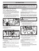
SAFETY RULES Safe Operation Practices for Ride-On Mowers III. SLOPE OPERATION • • • • WARNING! When loading or unloading this machine, do not exceed the maximum recommended operation angle of 15°. • Slopes are a major factor related to loss of control and tip-over accidents, which can result in severe injury or death. Operation on all slopes requires extreme caution. If you cannot back up the slope or if you feel uneasy on it, do not mow it. • Mow up and down slopes, not across.
PRODUCT SPECIFICATIONS Gasoline Capacity and type: 4 Gallons/15,14 L Regular Unleaded Oil Type: (API: SJ-SN) SAE 30 (above 32°F/0°C) SAE 5W30 (below 32°F/0°C) Oil Capacity: W/Filter: 64 Oz./1,89 L W/out Filter: 52 Oz./1,5 L Spark Plug: BPR4ES (Gap: .030"/0,76 mm) Spark Plug Torque: 16 ft-lb (22 Nm) Charging System: 15 Amps @ 3600 RPM Battery: Amp/Hr: Min. CCA: Case size: Blade Bolt Torque: 45-55 Ft. Lbs./62-75 Nm CONGRATULATIONS on your purchase of a new tractor.
UNASSEMBLED PARTS Keys (2) Keys Slope Sheet (1) Quick Connect (1) Oil Drain Tube For Future Use Battery *Installed by Dealer *Brush Guard Kit (2) Hex Bolts (2) Nut Keps ASSEMBLY Your new tractor has been assembled at the factory with exception of those parts left unassembled for shipping purposes. TOOLS REQUIRED FOR ASSEMBLY NOTE: If this battery is put into service after month and year indicated on label (label is located between terminals) charge battery for minimum of one hour at 6-10 amps.
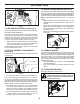
ASSEMBLY TO ADJUST THE SEAT (See Fig. 2) CHECK FOR PROPER POSITION OF ALL BELTS • Lift seat up and remove seat adjustment knob (A). • Loosen seat adjustment knob (B). NOTE: Do not remove seat adjustment knob (B). NOTE: Seat must be set until you can push the brake and forward/reverse pedals down. • Move seat to necessary position, line up the hole in the seat pan for seat adjustment knob (A) with the hole in the seat. • Install and tighten seat adjustment knob (A). • Tighten seat adjustment knob (B).
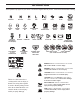
OPERATION These symbols may appear on your tractor or in literature supplied with the product. Learn and understand their meaning.
OPERATION KNOW YOUR TRACTOR READ THIS MANUAL AND SAFETY RULES BEFORE OPERATING YOUR TRACTOR Compare the illustrations with your tractor to familiarize yourself with the locations of various controls and adjustments. Save this manual for future reference. P Z E H D G F B N Q A C J K L M Fig. 3 Our tractors conform to the applicable safety standards of the American National Standards Institute.
OPERATION The operation of any tractor can result in foreign objects thrown into the eyes, which can result in severe eye damage. Always wear safety glasses or eye shields while operating your tractor or performing any adjustments or repairs. We recommend standard safety glasses or a wide vision safety mask worn over spectacles. HOW TO USE YOUR TRACTOR • TO SET PARKING BRAKE (See Fig. 4) • Your tractor is equipped with an operator presence sensing switch.
OPERATION TO ADJUST GAUGE WHEELS (See Fig. 9) J K Gauge wheels are properly adjusted when they are slightly off the ground when mower is at the desired cutting height in operating position. Gauge wheels then keep the deck in proper position to help prevent scalping in most terrain conditions. NOTE: Adjust gauge wheels with tractor on a flat level surface. • Adjust mower to desired cutting height (See “TO ADJUST MOWER CUTTING HEIGHT” in this section of manual).
OPERATION REVERSE OPERATION SYSTEM (ROS) (See Fig. 11) TO TRANSPORT (See Fig. 12) When pushing or towing your tractor, ensure transmission is disengaged by placing freewheel control in freewheeling position. Free wheel control is located at the rear drawbar of tractor. • Raise attachment lift to highest position with attachment lift control. • Pull freewheel control out and into the slot and release so it is held in the disengaged position. • Do not push or tow tractor at more than two (2) mph (3,2 km/h).
OPERATION ADD GASOLINE • WARM WEATHER STARTING (50°F/10°C and above) • When engine starts, slowly push choke control in until the engine begins to run smoothly. If the engine starts to run roughly, pull the choke control out slightly for a few seconds and then continue to push the control in slowly. • The attachments and ground drive can now be used. If the engine does not accept the load, restart the engine and allow it to warm up for one minute using the choke as described above.
OPERATION • 4. Depress forward drive pedal to full forward position, hold for five (5) seconds and release pedal. Depress reverse drive pedal to full reverse position, hold for five (5) seconds and release pedal. Repeat this procedure three (3) times. 5. Shut- off engine and set parking brake. 6. Engage transmission by placing freewheel control in engaged position. (See “TO TRANSPORT” in this section of manual.) 7. Sitting in the tractor seat, start engine.
MAINTENANCE MAINTENANCE SCHEDULE BEFORE EACH USE EVERY 8 HOURS EVERY 25 HOURS EVERY 50 HOURS EVERY 100 HOURS EVERY SEASON BEFORE STORAGE Check Brake Operation Check Tire Pressure T R A C T O R Check Operator Presence and ROS Systems Check for Loose Fasteners Check/Replace Mower Blades 3 Lubrication Chart Check Battery Level 4 Clean Battery and Terminals Clean Debris off Steering Plate 5 Check Transaxle Cooling Check Mower Levelness Check V-Belts Check Engine Oil Level Change Engine Oil (mode
MAINTENANCE TRACTOR BLADE CARE For best results mower blades must be kept sharp. Replace bent or damaged blades. Always observe safety rules when per form ing any maintenance. BRAKE OPERATION If tractor requires more than five (5) feet (1,5 m) to stop at highest speed in highest gear on a level, dry concrete or paved surface, then brake must be checked and adjusted. (See “TO CHECK BRAKE” in the Service and Adjustments section of this manual.
MAINTENANCE V-BELTS LOWER DASH COVER REMOVAL • Raise hood. • Remove fastener from lower dash cover. Check V-belts for deterioration and wear after 100 hours of operation and replace if necessary. The belts are not adjustable. Replace belts if they begin to slip from wear. CAUTION: Remove lower dash cover carefully to ensure cover tabs are not broken. TRANSAXLE MAINTENANCE • The transmission fan and cooling fins should be kept clean to ensure proper cooling.
MAINTENANCE CLEANING AIR FILTER Your engine will not run properly using a dirty air filter. Service air cleaner more often under dusty conditions. See engine manual. • • CLEAN AIR SCREEN The air screen is over the air intake blower located on top of engine. The air screen must be kept free of dirt and chaff to prevent engine damage from overheating. Clean with a wire brush or compressed air to remove dirt and stubborn dried gum fibers. Clean engine, battery, seat, finish, etc. of all foreign matter.
MAINTENANCE DECK WASHOUT PORT (See Fig. 21) Your tractor’s deck is equipped with a washout port as part of its deck wash system. It should be utilized after each use. 1. Drive the tractor to a level, clear spot on your lawn, near enough to a water spigot for your garden hose to reach. IMPORTANT: Make certain the tractor’s discharge chute is directed AWAY from your house, garage, parked cars, etc. Remove bagger chute or mulch cover if attached. 2.
SERVICE AND ADJUSTMENTS WARNING: TO AVOID SERIOUS INJURY, BEFORE PERFORMING ANY SERVICE OR ADJUSTMENTS: • Depress brake pedal fully and set parking brake. • Place attachment clutch in “DISENGAGED” position. • Turn ignition key to “STOP” and remove key. • Ensure the blades and all moving parts have completely stopped. • Disconnect spark plug wire from spark plug and place wire where it cannot come in contact with plug. TO REMOVE MOWER (See Fig. 22) • • • • • • TO INSTALL MOWER (See Fig.
SERVICE AND ADJUSTMENTS • • From right side of mower, first insert 90° end of anti-sway bar (S) into hole in transaxle bracket (T), located near left rear tire in front of transaxle. NOTE: Flashlight may be helpful. ANTI-SWAY BAR (S) LOCATION • ATTACH REAR LIFT LINKS (C) - Lift rear corner of mower and position slot in link assembly over pin on rear mower bracket (D) and secure with washer and retainer spring. Repeat on opposite side of tractor.
SERVICE AND ADJUSTMENTS TO LEVEL MOWER FRONT-TO-BACK ADJUSTMENT (See Figs. 32 & 33) IMPORTANT: Deck must be level side-to-side. Ensure tires are properly inflated to the PSI shown on tires. If tires are over or under inflated, it may affect the appearance of your lawn and lead you to think the mower is not adjusted properly.
SERVICE AND ADJUSTMENTS TO CHECK BRAKE MOWER DRIVE BELT INSTALLATION (See Fig. 35 & 36) NOTE: For ease in installing the deck belt, refer to the routing decal on the cutting deck. If tractor requires more than five (5) feet (1.5 m) to stop at highest speed in highest gear on a level, dry concrete or paved surface, then brake must be serviced. You may also check brake by: 1. Park tractor on a level, dry concrete or paved surface, depress brake pedal all the way down and engage parking brake. 2.
SERVICE AND ADJUSTMENTS TO REPLACE MOTION DRIVE BELT (See Fig. 37) BELT INSTALLATION 1. Install new belt from tractor rear to front, over the steering plate (H) and above clutch brake pedal shaft (J). 2. Pull belt toward front of tractor and roll belt around electric clutch and onto engine pulley (G). 3. Pull belt toward rear of tractor. Carefully work belt down around transmission cooling fan and onto the input pulley (F). Be sure belt is inside the belt keeper. 4. Install belt on centerspan idler (E). 5.
SERVICE AND ADJUSTMENTS TO START ENGINE WITH A WEAK BATTERY (See Fig. 39) • • WARNING: Lead-acid batteries generate explosive gases. Keep sparks, flame and smoking materials away from batteries. Always wear eye protection when around batteries. • First connect RED battery cable to positive (+) battery terminal with bolt and nut as shown. Tighten securely. Connect BLACK grounding cable to negative (-) battery terminal with remaining bolt and nut. Tighten securely Close hood.
SERVICE AND ADJUSTMENTS TO REMOVE HOOD AND GRILL ASSEMBLY (See Fig. 41) • • • • Raise hood. Unsnap headlight wire connector. Stand in front of tractor. Grasp hood at sides, tilt toward engine and lift off of tractor. To replace, reverse above procedure. HOOD HEADLIGHT WIRE CONNECTOR 07002 Fig.
STORAGE ENGINE Immediately prepare your tractor for storage at the end of the season or if the tractor will not be used for 30 days or more. FUEL SYSTEM IMPORTANT: IT IS IMPORTANT TO PREVENT GUM DEPOSITS FROM FORMING IN ESSENTIAL FUEL SYSTEM PARTS SUCH AS CARBURETOR, FUEL FILTER, FUEL HOSE, OR TANK DURING STORAGE. ALSO, EXPERIENCE INDICATES THAT ALCOHOL BLENDED FUELS (CALLED GASOHOL OR USING ETHANOL OR METHANOL) CAN ATTRACT MOISTURE WHICH LEADS TO SEPARATION AND FORMATION OF ACIDS DURING STORAGE.
TROUBLESHOOTING PROBLEM CAUSE CORRECTION 8. Loose or damaged wiring. 9. Engine valves out of adjustment. Fill fuel tank. See “TO START ENGINE” in Operation section. Wait several minutes before attempting to start. Replace spark plug. Clean/replace air filter. Replace fuel filter. Empty fuel tank and carburetor, refill tank with fresh gasoline and replace fuel filter. 8. Check all wiring. 9. Contact an authorized service center/department. Hard to start 1. 2. 3. 4. 5. 6. 7. Dirty air filter.
TROUBLESHOOTING PROBLEM CAUSE CORRECTION Engine continues to run when operator leaves seat with attachment clutch engaged 1. Faulty operator-safety presence control system. Poor cut - uneven 1. 2. 3. 4. 5. Worn, bent or loose blade. Mower deck not level. Buildup of grass, leaves, trash under mower. Bent blade mandrel. Clogged mower deck vent holes from buildup of grass, leaves, and trash around mandrels. 1. 2. 3. 4. 5. Replace blade. Tighten blade bolt. Level mower deck.
SUGGESTED GUIDE FOR SIGHTING SLOPES FOR SAFE OPERATION FOL DA L O NG D THIS O I T S T A E D LIN 1 5 DEG E RE E S LOP E ONLY RIDE UP AND DOWN HILL, NOT ACROSS HILL 15 DEGREES MAX. WARNING: To avoid serious injury, operate your tractor up and down the face of slopes, never across the face. Do not mow slopes greater than 15 degrees. Make turns gradually to prevent tipping or loss of control. Exercise extreme caution when changing direction on slopes. 1. Fold this page along dotted line indicated above. 2.
REGLAS DE SEGURIDAD Prácticas de Operación Seguras para las Segadoras Conducibles PELIGRO: ESTA MAQUINA CORTADORA ES CAPAZ DE AMPUTAR LAS MANOS Y LOS PIES Y DE LANZAR OBJETOS. SI NO SE OBSERVAN LAS INSTRUCCIONES DE SEGURIDAD SIGUIENTES SE PUEDEN PRODUCIR LESIONES GRAVES O LA MUERTE.
REGLAS DE SEGURIDAD Prácticas de Operación Seguras para las Segadoras Conducibles • • Mantener la máquina libre de hierba, hojas u otros escombros que pueden tocar el tubo de escape / partes del motor calientes y quemarse. No permitir que el puente del cortacésped cargue hojas u otros residuos que pueden causar acumulaciones. Limpiar toda salpicadura de aceite o carburante antes de hacer operaciones sobre la máquina o guardarla. Dejarla enfriar antes de guardarla. • • • • • III.
ESPECIFICACIONES DEL PRODUCTO Capacidad y Tipo de Gasolina: 15,14 L / 4 Galones Regular Sin Plomo Tipo de Aceite (API: SJ-SN): SAE 30 (sobre 32°F/0°C) SAE 5W30 (deabajo 32°F/0°C) Capacidad de Aceite: Con Filtro: Sin Filtro: Bujía BPR4ES (Abertura: 0,76 mm / .030") Par de apriete de la bujía: 16 ft-lb (22 Nm) Sistema de Carga: 15 Amps @ 3600 RPM Batería: Amp/Hr: Min. CCA: Modelo Tamaño: Torsión del Perno de la Cuchilla: 62-75 Nm 45-55 Ft. Lbs. FELICITACIONES por la compra de su tractor.
PEDAZOS PARA LA MONTAJE Llaves (1) Accesorio del conexión (1) Tubo de desagüe (2) Llaves Hoja de pendiente Batería *Instalado por el distribuidor (2) Perno *Juego de cubierta (2) Tuerca MONTAJE Su tractor nuevo ha sido montado en la fábrica con la excepción de aquellas partes que no se han montado por razones de envío.
MONTAJE REVISIÓN DE LA POSICIÓN ADECUADA DE TODAS LAS CORREAS PARA AJUSTAR EL ASIENTO (Vea Fig. 2) • Levante el asiento y retire la perilla de ajuste de este (A). • Suelte la perilla de ajuste del asiento (B). NOTA: No retire la perilla de ajuste del asiento (B). NOTA: El asiento se debe ajustar hasta que pueda pisar los pedales de freno y de avance/retroceso. • Mueva el asiento a la posición necesaria, alinee el orificio en la base del asiento para la perilla de ajuste (A) con el agujero en el asiento.
OPERACIÓN Estos símbolos pueden aparecer sobre su tractor o en la literatura proporcionada con el producto. Aprenda y comprenda sus significados.
OPERACIÓN FAMILIARICESE CON SU TRACTOR LEA ESTE MANUAL DEL OPERARIO Y LAS REGLAS DE SEGURIDAD ANTES DE OPERAR SU TRACTOR Compare las ilustraciones con su tractor para familiarizarse con las ubicaciones de los diversos controles y ajustes. Guarde este manual para referencia en el futuro. P Z E H D G F B N Q A C J K L M Fig. 3 Nuestros tractores cumplen con los estándares de seguridad del American National Standard Institute.
OPERACIÓN La operación de cualquier tractor puede hacer que salten objetos extraños dentro de sus ojos, lo que puede producir daños graves en éstos. Siempre use anteojos de seguridad o protecciones para los ojos mientras opere su tractor o cuando haga ajustes o reparaciones. Recomendamos gafas de seguridad o una máscara de visión amplia de seguridad usada sobre las gafas. COMO USAR SU TRACTOR PARA AJUSTAR EL FRENO DE ESTACIONAMIENTO (Vea Fig.
OPERACIÓN • Para obtener el mejor rendimiento de corte, el césped que tiene más de 152,4 mm (6 pulgadas) de altura debe segarse dos veces. Haga el primer corte relativamente alto; el segundo a la altura deseada. PARA AJUSTAR LAS RUEDAS CALIBRADORAS (Vea Fig. 9) J K Las ruedas calibradoras están bien ajustadas cuando se encuentran un poco a distancia del terreno al mismo tiempo que la segadora esté a la altura de corte deseada.
OPERACIÓN FUNCIONAMIENTO ATRÁS (ROS) (Vea Fig. 11) PARA TRANSPORTAR (Vea Fig. 12) Tu tractor está equipado con el Sistema de Funcionamiento Atrás (ROS). Cualquier tentativa del operador de viajar marcha atrás con el embrague puesto apagará el motor a menos que la llave de ignición se ponga en la posición de “ON” del ROS. Cuando empuje o arrastre su tractor asegúrese de desenganchar la transmisión poniendo el control de la rueda libre en la posición de marcha de rueda libre.
OPERACIÓN • AGREGUE GASOLINA • Llene el tanque de combustible hasta la parte inferior del cuello de relleno. No lo llene de más. Use gasolina normal nueva y limpia con un mínimo de 87 octanos. No mezcle aceite con gasolina. Compre combustible en cantidades que se puedan usar en 30 días para asegurar la frescura del combustible. PRECAUCIÓN: Limpie el aceite o el combustible derramado. No almacene, derrame o use gasolina cerca de una llama expuesta.
OPERACIÓN 3. Sentado en el asiento del tractor, empiece el motor. Después que este corriendo el motor, mueva el control de estrangulación a la posición de lento. Quitar el freno de mano. • • PRECAUCIÓN: En el transcurso del paso 4, puede que de pronto se pongan en movimiento las ruedas. 4. Apretar el pedal de marcha adelante hasta el fondo, mantener por cinco (5) segundos y soltar el pedal. Apretar el pedal de marcha atrás hasta el fondo, mantener por cinco (5) segundos y soltar el pedal.
MANTENIMIENTO PROGRAMA DE MANTENIMIENTO ANTES DE CADA USO CADA 8 HORAS CADA 25 HORAS CADA 50 HORAS CADA 100 HORAS CADA TEMPORADA ALMACENAMIENTO Revisar la operación del freno Revisar la presión de las llantas T R A C T O R Verificar la sistemas presencia del operador y sistemas "ROS" Revisar si hay sujetadores sueltos Afilar/cambiar las cuchillas de la segadora 3 Tabla de lubricación Revisar el nivel de bateria 4 Limpiar la batería y los tereminales Limpie los residuos de la placa de dirección
MANTENIMIENTO TRACTOR PRECAUCIÓN: Usar solamente la hojas de repuesto aprobada por el fabricante de su cortacésped. Usar una hoja no aprobada por el fabricante de su cortacésped es peligroso, puede dañar su cortacésped y anular su garantía. Siempre observe las reglas de seguridad cuando dé mantenimiento.
MANTENIMIENTO EXTRACCIÓN DE LA CUBIERTA DEL TABLERO INFERIOR • Levantar la capota. • Retirar el sujetador de la cubierta del tablero inferior. PRECAUCIÓN: Retirar la cubierta del tablero inferior con cuidado para que no se rompan las lengüetas de la cubierta. • Deslizar la cubierta del tablero inferior hacia arriba para liberar las lengüetas de la cubierta de las ranuras cónicas del tablero inferior y retirarla.
MANTENIMIENTO FILTRO DEL AIRE LIMPIEZA Su motor puede sufrir averías y funcionar de manera incorrecta con un filtro del aire sucio. Déle servicio al filtro de aire más a menudo si se usa en condiciones polvorosas. Vea la manual de la motor. • • LIMPIEZA DE LA PANTALLA DE AIRE La pantalla de aire está sobre el soplador de la toma de aire que se ubica en la parte superior del motor. La pantalla de aire se debe mantener libre de suciedad y paja para evitar que el motor se dañe por sobrecalentamiento.
MANTENIMENTO PUERTO DE LAVADO DE LA CUBIERTA (Vea Fig. 21) La plataforma del tractor está equipada con un puerto de lavado como parte del sistema de lavado de la plataforma. Se debe utilizar después de cada uso. 1. Lleve el tractor a un lugar horizontal y despejado de su césped, lo bastante cerca de una boca de riego como para que llegue la manguera del jardín. IMPORTANTE: Asegúrese de que la boca de descarga del tractor está orientada LEJOS de su casa, garaje, coches aparcados, etc.
SERVICIO Y AJUSTES ADVERTENCIA: PARA EVITAR LESIÓNES SERIAS, ANTES DE DAR CUALQUIER SERVICIO O DE HACER AJUSTES: • Presione el pedal del embrague/freno completamente y aplique el freno de estacionamiento. • Ponga la palanca de control de movimiento en la posición de neutro (N). • Ponga el embrague del accesorio en la posición desenganchado (DISENGAGED). • Ponga la llave de ignición en la posición de apagado (STOP) y remuévala.
SERVICIO Y AJUSTES • • Desde el lado derecho de la cortadora de césped, inserte primero el extremo en 90° de la barra antibalanceo (S) dentro del agujero de la escuadra de transeje (T), ubicado cerca de la rueda trasera izquierda adelante del transeje. AVISO: Puede resultar útil usar una linterna.
SERVICIO Y AJUSTES TO LEVEL MOWER FRONT-TO-BACK ADJUSTMENT (See Figs. 32 & 33) IMPORTANT: Deck must be level side-to-side. Ensure tires are properly inflated to the PSI shown on tires. If tires are over or under inflated, it may affect the appearance of your lawn and lead you to think the mower is not adjusted properly.
SERVICIO Y AJUSTES CONTROLAR Y AJUSTAR EL FRENO INSTALACIÓN DE LA CORREA (Vea Fig. 35 y 36) AVISO: Para facilitar la instalación de la cinta de la plataforma, consulte la etiqueta sobre la ruta que está en la plataforma de corte. • Coloque la correa alrededor todas las poleas. • Vuelva a revisar la ruta de la cinta para asegurarse de que coincida con la etiqueta sobre la ruta, y que la cinta no esté torcida. Corrija si es necesario.
SERVICIO Y AJUSTES PARA CAMBIAR LA CORREA DE IMPULSIÓN DE MOVIMIENTO (Vea Fig. 37) MONTAJE DE LA CORREA 1. Instale la correa nueva pasándola de la parte de atrás a la parte de adelante del tractor, por encima de la placa de dirección (H) y del vástago del pedal del embrague / freno (J). 2. Jale la correa hacia la parte de adelante del tractor y pásela alrededor del embrague y por sobre la polea del motor (G). 3. Jale la correa hacia la parte de atrás del tractor.
SERVICIO Y AJUSTES PARA HACER ARRANCAR EL MOTOR CON UNA BATERÍA BAJA (Vea Fig. 39) • • ADVERTENCIA: Las baterías de ácido-plomo generan gases explosivos. Mantenga las chispas, las llamas y los materiales para fumar alejados de las baterías. Siempre use una protección para los ojos alrededor de las baterías. • Primero, conecte el cable de la batería ROJO con el terminal positivo (+) con el perno hexagonal y la tuerca según se muestra. Apriételos en forma segura.
SERVICIO Y AJUSTES PARA REMOVER EL CONJUNTO DEL CAPÓ Y DEL ENREJADO (Vea Fig. 41) 1. Levante el capó. 2. Desabroche el conector del alambre de las luces delanteras. 3. Párese delante del tractor. Agarre el capó en los lados, inclínelo un poco hacia el motor y sáquelo del tractor. 4. Para volver a instalar el capó, asegúrese de volver a conectar el conector del alambre de las luces. CAPOTA CONECTOR DEL ALAMBRE DE LAS LUCES DELANTERAS 07002 Fig.
ALMACENAMIENTO MOTOR Inmediatamente prepare su tractor para el almacenamiento al final de la temporada o si el tractor no se va a usar por 30 días o más.
IDENTIFICACIÓN DE PROBLEMAS PROBLEMA No arranca CAUSA CORRECCIÓN 3. 4. 5. 6. 7. Sin combustible. Motor sin la “ESTRANGULACIÓN” (CHOKE) adecuada. Motor ahogado. Bujía mala. Filtro de aire sucio. Filtro de combustible sucio. Agua en el combustible. 3. 4. 5. 6. 7. 8. 9. Alambrado suelto o dañado. Válvulas del motor desajustadas. 8. 9. 1. 2. 3. 4. 5. Filtro de aire sucio. Bujía mala. Batería baja o descargada. Filtro de combustible sucio. Combustible rancio o sucio. 1. 2. 3. 4. 5. 6. 7.
IDENTIFICACIÓN DE PROBLEMAS PROBLEMA CAUSA El motor continúa funcionando cuando el operador se baja del asiento con el embrague del accesorio enganchado 1. El corte disparejo 1. 2. 3. Mala descarga del césped 1. Revise el alambrado, los interruptores y la conexiones.Si no están correctas, pongase en contacto con un centro de servicio cualificado. PRECAUCIÓN: NO opere la máquina sino hasta haber corregido el problema. Cuchilla desgastada, doblada o suelta. El conjunto segador no estánivelado.
GUÍA SUGERIDA PARA MEDIR LAS PENDIENTES CON LA VISTA PARA UNA OPERACIÓN SEGURA PL E G AR A LO EST L A RGO A ES DE U N L A A PEN LÍNE DIE A P N U T NTE E DE ADA 1 5 GRA DOS SOLAMENTE ANDE CUESTA ARRIBA O CUESTA ABAJO Y NO ATRAVIESE EL CERRO 15 GRADOS MAX. ADVERTENCIA: Para evitar daños graves, haga funcionar su tractor arriba y abajo de las pendientes, nunca transversalmente con respecto a las pendientes. No cortar pendientes mayores de 15 grados.
SERVICE NOTES/AVISO 58
SERVICE NOTES/AVISO 59
09.03.19 CL Printed in U.S.A.