OWNER’S MANUAL TS 20 8 H.P. 30" (76,2 cm) SLEEVE HITCH TILLER ATTACHMENT MODEL NUMBER TS200FR 02480 169689 Rev. 2 4.11.03 TR Printed in U.S.A.
SAFETY RULES Safe Operation Practices for Tiller Attachments. TRAINING • Read the operating and service instruction manual carefully. Be thoroughly familiar with the controls and the proper use of the equipment. Know how to stop the unit and disengage the controls quickly. • Never allow children to operate the equipment. Never allow adults to operate the equipment without proper instruction. • Keep the area of operation clear of all persons, par ticularly small children, and pets.
PRODUCT SPECIFICATIONS GASOLINE CAPACITY: CUSTOMER RESPONSIBILITIES • • 1 GALLON (3,6L) UNLEADED REGULAR OIL : SAE30W (ABOVE 32°F/0°C) (CAPACITY: 24 OZ. [0.7L]) 5W-30 (BELOW 32°F/0°C) TRANSMISSION OIL : SAE 30W • IMPORTANT: THIS UNIT IS EQUIPPED WITH AN INTERNAL COMBUSTION ENGINE AND SHOULD NOT BE USED ON OR NEAR ANY UNIMPROVED FOREST-COVERED, BRUSHCOVERED OR GRASS COVERED LAND UNLESS THE ENGINE'S EXHAUST SYSTEM IS EQUIPPED WITH A SPARK ARRESTER MEETING APPLICABLE LOCAL OR STATE LAWS (IF ANY).
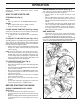
ASSEMBLY • Adjust stabilizer bolts so that ends are about flush with rear of hitch bail (Fig. 2 - Inset). Leave nuts loose. • Lower hitch assembly and slide hitch yoke of tiller (Fig. 2 - Inset) over hitch tube of sleeve hitch so that the hitch pin holes line up. • Insert hitch pin until it extends from bottom of hitch yoke (Fig. 2 - Inset). Insert retainer spring into hitch pin. • Tighten both stabilizer bolts against the hitch yoke until there is no looseness at the hitch point.
OPERATION IMPORTANT: READ THE “RULES FOR SAFE OPERATION” CAREFULLY BEFORE OPERATING YOUR TILLER ATTACHMENT. CHECK ENGINE OIL LEVEL (See Fig. 1) The engine on your tiller has been shipped from the factory, already filled with summer weight oil. • Check engine oil with engine leveled on level ground. • Remove dipstick and wipe clean, replace, wait for a few seconds, remove and read oil level. If necessary, add oil until “FULL” mark on dipstick is reach. Do not overfill.
OPERATION NOTE: If at a high altitude (Above 3000 feet) or in cold temperatures (below 32°F), the carburetor fuel mixture may need to be adjusted for best engine performance. See “TO ADJUST CARBURETOR” in the Service and Adjustments section of this manual. CAUTION: Fill to bottom of gas tank filler neck. Do not overfill. Wipe off any spilled oil or fuel. Do not store, spill or use gasoline near an open flame.
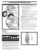
MAINTENANCE SCHEDULE FILL IN DATES AS YOU COMPLETE REGULAR SERVICE BE FO RE EA FIR CH ST US 2H E EV OU ER RS Y5 HO EV ER UR Y2 S 5H EV OU ER RS Y5 0H EV OU ER RS Y1 00 BE HO FO UR RE S ST OR AG E CUSTOMER RESPONSIBILITIES SERVICE DATES Check Engine Oil Level Change Engine Oil Oil Pivot Points Inspect Spark Arrester / Muffler Inspect Air Screen Clean Air Filter/Foam Pre-Cleaner 2 Clean Engine Cylinder Fins Replace Air Filter/Paper Cartridge Replace Spark Plug 1 - Change more often when operating under
CUSTOMER RESPONSIBILITIES TO CHANGE ENGINE OIL (See Figs. 6 and 7) Determine temperature range expected before oil change. All oil must meet API service classification SF or SG. • Be sure tiller engine is level. • Oil will drain more freely when warm. • Catch oil in a suitable container. • Remove drain plug. • Tip tiller forward to drain oil. • After oil has drained completely, replace oil drain plug and tighten securely. • Remove oil filler plug. Be careful not to allow dirt to enter the engine.
CUSTOMER RESPONSIBILITIES COOLING SYSTEM (See Fig. 9) Your engine is air cooled. For proper engine performance and long life keep your engine clean. • Clean air screen frequently using a stiff bristled brush. • Remove blower housing and clean as necessary. • Keep cylinder fins free of dirt and chaff. MUFFLER Do not operate tiller without muffler. Do not tamper with exhaust system. Damaged mufflers or spark arresters could create a fire hazard. Inspect periodically and replace if necessary.
SERVICE AND ADJUSTMENTS CAUTION: Disconnect spark plug wires from spark plug and place wire where it cannot come into contact with plug. TILLER TO ADJUST GAUGE WHEELS See “TO ADJUST TILLING DEPTH” in Operation section of this manual. TO ADJUST BELT (See Fig. 10) The clutch is a belt-tightener type. Belt should be just tight enough to prevent slipping. Over-tightening will reduce belt life. • To tighten belt, remove retainer spring securing belt tightener link to clutch lever and arm.
SERVICE AND ADJUSTMENTS IDLE RPM ADJUSTMENT• With engine at idle speed, turn the idle adjust screw slowly counterclockwise until the engine begins to falter. • Then raise the engine speed by turning the idle adjust screw clockwise until the engine holds a smooth constant speed. ENGINE TO ADJUST CARBURETOR (See Fig. 11) The carburetor has been preset at the factory and adjustment should not be necessary.
STORAGE Immediately prepare your tiller for storage at the end of the season or if the unit will not be used for 30 days or more. ENGINE OIL Drain oil (with engine warm) and replace with clean oil. (See “ENGINE” in the Customer Responsibilities section of this manual). CAUTION: Never store the tiller with gasoline in the tank inside a building where fumes may reach an open flame or spark. Allow the engine to cool before storing in any enclosure.
TROUBLESHOOTING POINTS PROBLEM Will not start CAUSE CORRECTION 1. 2. 3. 4. 5. Out of fuel. Engine not “CHOKED” properly. Engine flooded. Dirty air cleaner. Water in fuel. 1. 2. 3. 4. 5. 6. 7. 8. 9. Clogged fuel tank. Loose spark plug wire. Bad spark plug or improper gap. Carburetor out of adjustment. 6. 7. 8. 9. Fill fuel tank. See “TO START ENGINE” in Operation section. Wait several minutes before attempting to start. Replace air cleaner cartridge.
REPAIR PARTS 8 HP TILLER ATTACHMENT - - MODEL NUMBER TS200FR ENGINE AND TINES 14
REPAIR PARTS 8 HP TILLER ATTACHMENT - - MODEL NUMBER TS200FR ENGINE AND TINES KEY NO. PART DESCRIPTION KEY NO. NO.
REPAIR PARTS 8 HP TILLER ATTACHMENT - - MODEL NUMBER TS200FR TRANSMISSION AND GAUGE WHEELS 16
REPAIR PARTS 8 HP TILLER ATTACHMENT - - MODEL NUMBER TS200FR TRANSMISSION AND GAUGE WHEELS KEY NO. PART DESCRIPTION NO.
02480