2007 4213 Utility Vehicle Gasoline Owner’s Manual HUV 4213-G HUV 4213-GXP
NOTICE The Husqvarna® Limited Two Year Warranty for 2007 Transportation and Utility Vehicles and California Emission Control Warranty Statement appear on the last pages of this manual. No other warranties, express or implied, are contained herein. Please complete and return the warranty registration card included in this manual. Husqvarna is not liable for errors in this manual or for incidental or consequential damages that result from the use of the material in this manual.
FOREWORD Thank you for choosing Husqvarna, a world leader in outdoor products. You have chosen the finest utility vehicle on the market. Please protect your investment and ensure that your Husqvarna vehicle provides years of reliable, superior performance by reading and following the maintenance instructions in this manual. Your comfort and safety are important to us, so we urge you to read and follow the step-by-step operating instructions and safety precautions in this manual.
TABLE OF CONTENTS Vehicle Feature Identification .................................................................................................................... 4 Safety Details ............................................................................................................................................ 7 General Warnings ...................................................................................................................................... 8 Model Identification .....
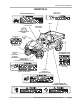
Vehicle Feature Identification HUV4213-G DIFFERENTIAL LOCK CONTROL DECAL OPERATING INSTRUCTIONS DECAL DRIVER/PASSENGER WARNING DECAL KEY SWITCH BED LOAD WARNING DECAL UNDERAGE WARNING DECAL FUEL SHUT-OFF VALVE (ON TOP OF FUEL TANK) LAMP SWITCH FUEL GAUGE/ HOUR METER LOW OIL WARNING LAMP SERIAL NUMBER CRUSH AREA DECAL BRAKE PEDAL BED LATCH ACCELERATOR PEDAL VEHICLE LOADING DECAL Page 4 (UNDER SEAT SUPPORT) 2007 HUV4213 Gasoline Vehicle Owner’s Manual ROTATING PARTS DECAL (TOP OF PASSENGER SI
Vehicle Feature Identification HUV4213-G BED LATCH WARNING DECAL GASOLINE WARNING DECAL CHOKE (ON PASSENGER SIDE SEAT SUPPORT) PARK BRAKE (DOTTED LINE) FORWARD/REVERSE HANDLE TRAILER HITCH DECAL (ON FRONT AND REAR RECEIVER HITCHES) RECEIVER HITCH (SHOWN WITH OPTIONAL TUBE BUMPER) ROTATING PARTS AND HOT MANIFOLD DECAL WINCH CABLE WARNING DECAL (FOR VEHICLES WITH WINCH ACCESSORY) (ON STARTER/GENERATOR AND ENGINE) (ON SEAT SUPPORT PANEL) DIODE WIRING DECAL (ON FRAME ABOVE DIODE) FRAME GROUND AND
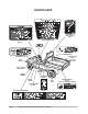
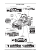
HUV4213-GXP DIFFERENTIAL LOCK CONTROL DECAL OPERATING INSTRUCTIONS DECAL DRIVER/PASSENGER WARNING DECAL KEY SWITCH BED LOAD WARNING DECAL UNDERAGE WARNING DECAL FUEL SHUT-OFF VALVE (ON TOP OF FUEL TANK) LAMP SWITCH FUEL GAUGE/ HOUR METER LOW OIL WARNING LAMP SERIAL NUMBER CRUSH AREA DECAL BRAKE PEDAL BED LATCH ACCELERATOR PEDAL VEHICLE LOADING DECAL Page 6 (UNDER SEAT SUPPORT) 2007 HUV4213 Gasoline Vehicle Owner’s Manual ROTATING PARTS DECAL (TOP OF PASSENGER SIDE FENDER)
HUV4213-GXP BED LATCH WARNING DECAL GASOLINE WARNING DECAL CHOKE (ON PASSENGER SIDE SEAT SUPPORT) PARK BRAKE (DOTTED LINE) FORWARD/REVERSE HANDLE TRAILER HITCH DECAL (ON FRONT AND REAR RECEIVER HITCHES) ROTATING PARTS AND HOT MANIFOLD DECAL RECEIVER HITCH WINCH CABLE WARNING DECAL (FOR VEHICLES WITH WINCH ACCESSORY) (ON STARTER/GENERATOR AND ENGINE) (ON SEAT SUPPORT PANEL) DIODE WIRING DECAL (ON FRAME ABOVE DIODE) FRAME GROUND AND GOVERNOR WARNING DECAL (ON FRAME) 2007 HUV4213 Gasoline Vehicle
Practice Safety ! WARNING Rotating Parts Safety signs like you see above may at first seem shocking, but their impact is mild compared with the reality of severe personal injury. Your safety and satisfaction are of the utmost importance to Husqvarna. That is why before operating the vehicle, we urge you to review the information in this manual.
Safety Details SAFETY DETAILS ý WARNING • This owner’s manual should be read completely before attempting to drive or service the vehicle. Failure to follow the instructions in this manual could result in property damage, severe personal injury, or death. It is important to note that some vital statements throughout this manual and on the decals affixed to the vehicle are preceded by the words DANGER, WARNING, or CAUTION.
General Warnings GENERAL WARNINGS The following safety statements must be heeded whenever the vehicle is being operated, repaired, or serviced. Vehicle feature identification information is also included beginning on page 4. Other specific safety statements appear throughout this manual and on the vehicle. ý DANGER • Battery – Explosive gases! Do not smoke. Keep sparks and flames away from the vehicle and service area. Ventilate when charging or operating vehicle in an enclosed area.
Model Identification ý WARNING • Frame ground – Do not allow tools or other metal objects to contact frame when disconnecting battery cables or other electrical wiring. Do not allow a positive wire to touch the vehicle frame, engine, or any other metal component. • Wear safety glasses or approved eye protection when servicing the vehicle. Wear a full face shield and rubber gloves when working on or near batteries. • Do not wear loose clothing or jewelry such as rings, watches, chains, etc.
Controls and Indicators CONTROLS AND INDICATORS See General Warnings on page 10. ý WARNING • Before allowing anyone to drive the vehicle, make sure the driver is familiar with all controls and operating procedures. • Do not tamper with the governor. Doing so will void the warranty, as well as damage the engine and other components, and could result in property damage, personal injury, or death due to unsafe speeds. • Do not shift the Forward/Reverse handle while the vehicle is in motion.
Controls and Indicators CAUT ION • Do not “rev” the engine for long periods of time while the Forward/Reverse handle is in the NEUTRAL position. Failure to heed this caution could result in damage to the unitized transaxle. • Do not shift the Forward/Reverse handle while the accelerator pedal is pressed. Shift the handle only when the vehicle is at a complete stop. Failure to heed this caution could result in damage to the unitized transaxle.
Controls and Indicators BRAKE PEDAL The brake pedal is the large pedal on the left with the word STOP molded into it (Figure 5). To slow or stop the vehicle, press the brake pedal (Figure 6). Figure 5 Accelerator and Brake Pedal Figure 6 Brake Pedal PARK BRAKE The park brake handle is located between the driver and passenger seats. To engage the park brake, first apply pressure to the brake pedal, and then pull up on the park brake handle until handle latches into place.
Controls and Indicators DIFFERENTIAL LOCK ý WARNING • With the differential lock engaged, vehicle turning functions are greatly reduced. To prevent loss of vehicle control when differential lock is engaged, do not operate vehicle at speeds greater than half throttle and use caution when attempting to turn the vehicle. • Disengage differential lock on paved surfaces. The differential lock is used to provide better traction at the rear wheels when necessary.
Seat Latch and Adjustment HEADLAMP CONTROL The headlamp control is located on the instrument panel between the fuel gauge/hour meter and steering column. Pull the headlamp control knob out to turn the headlamps on and push the knob in to turn the headlamps off. NOTE: Using the headlamps for extended periods of time without the engine running, or with the engine idling, will discharge the battery.
Performance Inspection • Fuel: Check fuel level. See Fueling Instructions on page 33. Check fuel tank, lines, fuel cap, pump, fuel filters, and carburetor for fuel leakage on a daily basis. • Exhaust system: Check for leaks. • Hydraulic brakes: Check fluid level. See Master Cylinder on page 29. PERFORMANCE INSPECTION After you have familiarized yourself with the vehicle controls and have read and understood the driving instructions, take the vehicle for a test drive.
Driving Instructions DRIVING INSTRUCTIONS ý WARNING • Only licensed drivers should be allowed to drive this vehicle. • Before allowing anyone to drive the vehicle, make sure the driver is familiar with all controls and operating procedures. • No one under the age of 16 years should be allowed to drive the vehicle. • No more than one person per bucket seat at one time, or two persons per bench seat. • Do not allow riders in the cargo bed.
Driving Instructions STARTING THE VEHICLE 1. Read safety warnings on dash and vehicle loading information located above pedals. 2. Be sure load, if any, is secure. 3. Study and understand controls. 4. Be sure all passengers are seated and holding on to hand holds. Driver should have both hands on the steering wheel. 5. Make sure wheels are turned in desired direction and nothing is in your path. 6. Make sure the Forward/Reverse handle is in the NEUTRAL position. 7. Press and hold the brake pedal. 8.
Bed Latch and Prop Rod PARKING AND LEAVING THE VEHICLE 1. After stopping the vehicle, set hand brake until it locks. Make sure it is fully engaged. This will prevent the vehicle from rolling. 2. Turn the key switch to the OFF position and place the Forward/Reverse handle in the NEUTRAL position. Remove the key and turn the fuel shut-off valve to the closed (OFF) position when the vehicle is not in use (Figure 12, Page 24). See also Figure 24 on page 34.
Front Shock Absorbers FRONT SHOCK ABSORBERS The vehicle arrives from the factory with the front coil-over shocks pre-adjusted for optimum vehicle performance. We do not recommend adjusting the shock absorbers unless the vehicle will be equipped with a cab enclosure. In that event, please refer to the cab installation instructions for the shock absorber adjustment procedure. LOADING AND UNLOADING ý WARNING • • • • • • • • • • • • Firmly engage park brake before loading vehicle.
Towing with the Vehicle TOWING WITH THE VEHICLE ý WARNING • Do not tow a vehicle or trailer on public streets or highways. • Normal vehicle operating speed should be reduced when towing. • Extreme caution should be used when towing. • Do not allow riders in the vehicle or trailer being towed. • Avoid sudden starts, sudden stops, and tight turns when towing. • Avoid stopping on a hill when towing. If you must stop on a hill, avoid sudden starts, or rolling backwards and stopping suddenly.
Storage STORAGE See General Warnings on page 10. ý DANGER • Do not attempt to drain gasoline when the engine is hot or while it is running. • Be sure to clean up any spilled gasoline before operating the vehicle. • Store gasoline in an approved gasoline container only. Store in a well-ventilated area away from sparks, open flames, heaters, or heat sources. • Keep gasoline out of the reach of children. • Do not siphon gasoline from the vehicle.
Storage CLOSED (OFF) POSITION (SELECTOR IS ALIGNED WITH OFF MARKINGS ON THE SIDES OF VALVE) OFF OFF VIEWED FROM SELECTOR SIDE OF VALVE Figure 12 Fuel Shut-off Valve – Closed Position 7. Disconnect the battery cables, negative (–) cable first. See WARNING “To avoid unintentionally starting...” on page 10. 8. Batteries should be clean and free of corrosion. Wash tops and terminals of batteries with a solution of baking soda and water (1 cup (237 mL) baking soda per 1 gallon (3.8 L) of water).
Maintenance 6. Connect battery cables, positive (+) cable first, and tighten terminals to 12 ft-lb (16 N·m). Coat terminals with Battery Terminal Protector Spray (P/N 603 00 00-03). 7. Completely open the fuel shut-off valve (Figure 13). Make sure the valve is fully open. A partially closed fuel shut-off valve combined with the use of the choke can result in a fouled spark plug and engine failure (Figure 14). 8. Place the Forward/Reverse handle in the NEUTRAL position.
Periodic Service Schedule ý WARNING • Only trained technicians should service or repair the vehicle. Anyone doing even simple repairs or service should have knowledge and experience in electrical and mechanical repair. The appropriate instructions must be used when performing maintenance, service, or accessory installation. • If any problems are found during scheduled inspection or service, do not operate vehicle until repairs are made.
Periodic Service Schedule PERIODIC SERVICE SCHEDULE REGULAR INTERVAL SERVICE Monthly service by owner or trained technician Check engine oil level; change if necessary. See Periodic Lubrication Schedule on page 28. Engine Semiannual service by trained technician only (or every 50 hours of operation, whichever comes first) Check engine cooling air intake; visually inspect unshrouded area around engine exhaust for grass and debris and clean if necessary.
Periodic Lubrication Schedule PERIODIC LUBRICATION SCHEDULE PERIODIC LUBRICATION SCHEDULE LUBRICATION POINTS REGULAR INTERVAL SERVICE Semiannually by owner or trained technician (or every 50 hours of operation, whichever comes first) Brake pedal shaft bearings 1 Dry Moly Lube (P/N 603 00 00-01) Accelerator push rod pivots, mounts, and shifter cable pivots 2 Dry Moly Lube (P/N 603 00 00-01) Front suspension (2 fittings) 3 Chassis Lube (EP NLGI Grade 2) Check/add brake fluid 4 Use only DOT 5
Master Cylinder NG NI ID R LY U WA E ON US 3 FL A T OM D ER DO FR ALE I N SE TA N CO MASTER CYLINDER Ful l Lev el L U AP ID S B FR EFO RE REM O O C OM A SEA LED E R C L L FI .O . N E R T. 3 F IN TA I V N G CLEA N U SE O N LY D MAX Safe Le vel MA X MIN MI N Low Lev el Figure 16 Brake Fluid Reservoir The master cylinder is located under the passenger bucket seat toward the center of the vehicle (Figure 16). Raise or remove the seat to check the brake fluid level.
Engine Oil 2 3 full level 1 safe level low level Level Oil fill tube is located behind and under passenger seat. Figure 17 Engine Oil Level Check – HUV4213 ENGINE OIL AND FILTER CHANGE Engine oil and oil filter should be changed after the first 100 hours of operation. After that, they should be changed every 200 hours of operation or annually, whichever comes first. 1. Turn the key switch to the OFF position then remove the key. Place the Forward/Reverse handle in the NEUTRAL position.
Engine Oil OIL FILTER DRAIN PAN DRAIN PLUG Figure 18 Engine Oil Drain Plug and Pan 9. Place a floor jack under the rear receiver hitch where the hitch and body frame are fastened. Lift the vehicle body slightly, allowing the front of the engine to tilt slightly downward. This will allow the oil filter more clearance under the electrical component box (Figure 19). 10. Relocate the oil drain pan to a position under the engine oil filter (Figure 18). 11.
Engine Oil Figure 21 Coat Rubber Seal Figure 22 Add Engine Oil NOTE: An oil drip guard can be used to prevent excess oil from dripping into the engine base plate. Use an empty quart (1 liter) container and cut the bottom off at an angle, then slide the open area of the container up and under the oil filter prior to removal. Position the port of the plastic container so oil will be directed into the oil pan (Figure 20).
Fueling Instructions OIL VISCOSITY Choose the viscosity according to the temperature as shown in the oil viscosity chart (Figure 23). -20° C -10° C 0° C 10° C 20° C 30° C 40° C SAE 40 SAE 30 SAE 10W-30/SAE 10W-40 SAE 5W-20 -4° F 14° F 32° F 50° F 68° F 86° F 104° F Figure 23 Oil Viscosity Chart NOTE: Using multi-grade oils (5W-20, 10W-30, and 10W-40) will increase oil consumption. Check oil level more frequently when using them. FUELING INSTRUCTIONS See General Warnings on page 10.
Battery NOTE: Whenever possible, avoid using oxygenated fuels and fuels that are blended with alcohol. Vehicles to be stored for extended periods should be prepared for storage as instructed. See Preparing the Vehicle for Extended Storage on page 23. 3. Replace fuel cap on the tank. Ensure cap is tightened securely. 4. Clean any spilled fuel from the tank top and around the tank area. 5. Replace passenger seat. ý WARNING • Make sure seat hinges and latch are securely engaged before operating vehicle.
Battery ý WARNING • Do not jump-start a dead battery using another battery and jumper cables. The battery in a Husqvarna vehicle is a 12-volt, low-maintenance battery that requires infrequent checks (Figure 25). Electrolyte level should be checked semiannually. 1. Turn the key switch to the OFF position and remove the key. Place the Forward/Reverse handle in the NEUTRAL position. Chock the wheels. 2. Access the engine compartment. See WARNING “For vehicles with cargo beds...” on page 10. 3.
Cleaning the Vehicle Be sure battery hold-down clamp is properly tightened. Tighten to 12 ft-lb (16 N·m). A loose clamp may allow the battery to become damaged from vibration or jarring. If battery appears weak, have it charged by a trained technician. The battery should never be left discharged any longer than absolutely necessary (do not leave discharged overnight). CLEANING THE VEHICLE Each vehicle is equipped with an ABS/DR acrylic front body and an all-aluminum rear body.
Subsequent Owner Registration ELECTRIC WINCH ACCESSORY If your vehicle is equipped with an electric winch, read and follow all manufacturer safety warnings and instructions in the winch operator manual, as well as the following WARNING and CAUTION statements. Make sure a winch warning decal is affixed to the vehicle on the seat support panel next to the receptacle for the remote operation switch. See Vehicle Feature Identification on beginning page 4.
Vehicle Specifications VEHICLE SPECIFICATIONS SPECIFICATIONS HUV4213-GXP HUV4213-G POWER SOURCE Engine: 4-cycle OHV, 400 cc, 13.
Vehicle Specifications SPECIFICATIONS HUV4213-GXP HUV4213-G DIMENSIONS/WEIGHT, Continued Seat height Load bed height Load bed size (box bed inside dimensions) Load bed size (flat bed dimensions) 35 in. (89 cm) 31.1 in. (79 cm) 48.0 x 49.8 x 10.9 in. (121.4 x 126.4 x 27.6 cm) (15.3 cubic feet) 46.9 x 48.3 in. (119 x 123 cm) Vehicle rated capacity (level surface only) 1200 lb. (544 kg) Bed load capacity (level surface only) 800 lb.
HUSQVARNA® LIMITED TWO YEAR WARRANTY FOR 2007 TRANSPORTATION AND UTILITY VEHICLES 1. WARRANTY: HUSQVARNA, INC.
6. DISCLAIMER: THIS LIMITED WARRANTY IS EXCLUSIVE. HUSQVARNA MAKES NO OTHER WARRANTY OF ANY KIND, EXPRESSED OR IMPLIED. ANY IMPLIED WARRANTIES OF MERCHANTABILITY OR FITNESS FOR A PARTICULAR PURPOSE WHICH EXCEED THE OBLIGATIONS OR TIME LIMITS STATED IN THIS WARRANTY ARE HEREBY DISCLAIMED BY HUSQVARNA AND EXCLUDED FROM THIS WARRANTY. THE PURCHASER AND HUSQVARNA EXPRESSLY AGREE THAT THE REMEDY OF THE REPLACEMENT OR REPAIR OF THE DEFECTIVE VEHICLE OR COMPONENT THEREOF IS THE SOLE REMEDY OF THE PURCHASER.
CALIFORNIA EMISSION CONTROL WARRANTY STATEMENT Your new Husqvarna, Inc. ("HUSQVARNA") vehicle engine complies with both the U.S. EPA and State of California emission regulations. YOUR WARRANTY RIGHTS AND OBLIGATIONS: The California Air Resources Board ("CARB") and HUSQVARNA are pleased to explain the emission control system warranty on your 2007 vehicle engine. In California, new small offroad engines (SORE) must be designed, built and equipped to meet the State's stringent anti-smog standards.
EMISSION CONTROL INFORMATION Fuel Information 2.Exhaust Emission Control System THIS VEHICLE IS CERTIFIED TO OPERATE ON UNLEADED REGULAR GRADE GASOLINE ONLY.A minimum of 87 octane of the anti-knock index is recommended.The antiknock index is posted on service station pumps in the U.S.A. The exhaust emission control system applied to this engine consists of a carburetor and an ignition system having optimum ignition timing characteristics.
Publication Part Number 531 30 81-87 Edition Code 0706A00000 CCI P/N 103218318