Operator Manual Commercial Mower W436 / 967334301-00 W448 / 967334401-00 Please read the operator manual carefully and make sure you understand the instructions before using the machine. Gasoline containing up to 10% ethanol (E10) is acceptable for use in this machine. The use of any gasoline exceeding 10% ethanol (E10) will void the product warranty.
WARNING! Failure to follow cautious operating practices can result in serious injury to the operator or other persons. The owner must understand these instructions, and must allow only trained persons who understand these instructions to operate the unit. Each person operating the mower must be of sound mind and body and must not be under the influence of any mind altering substance.
TABLE OF CONTENTS SYMBOLS AND DECALS........................5 SAFETY....................................................6 ASSEMBLY............................................10 CONTROLS............................................11 OPERATION...........................................12 MAINTENANCE SCHEDULE.................19 MAINTENANCE.....................................20 STORAGE..............................................26 TROUBLESHOOTING...........................27 2014 All rights reserved.
Emission Control System Operating This equipment and/or its engine may include exhaust and evaporative emissions control system components required to meet U.S. Environmental Protection Agency (EPA) and/ or California Air Resources Board (CARB) regulations. Tampering with emission controls and components by unauthorized personnel may result in severe fines or penalties. Emission controls and components can only be adjusted by a Husqvarna dealer or an authorized engine manufacturer's service center.
SYMBOLS AND DECALS These symbols are found on the machine and in the operator manual. Study them carefully so that you know what they mean. IMPORTANT Xxxx xxxxxx xxxxx xxxx xxxxxxxxx xxxxxx xxxxxxxxx. xx xxxxxxxx xxxx xxxxxx. WARNING! Xxxx xxxxxx xxxxx xxxx xxxxxxxxx xxxxxx xxxxxxxxx. xx xxxxxxxx xxxx xxxxxx. Used in this publication to notify the reader of a risk of personal injury or death, particularly if the reader should neglect to follow instructions given in the manual.
SAFETY Protecting Children obstacles can injure the operator or interfere with mowing operation. Before mowing, identify potential obstacles such as low-hanging branches, and trim or remove those obstacles. Tragic accidents can occur if the operator is not alert to the presence of children. Children are often attracted to the machine and the mowing activity. Never assume that children will remain where you last saw them.
Personal Safety Equipment Safe Handling of Gasoline • Make sure first aid equipment is close at hand when using the machine. • Never use the machine when barefoot. Always wear protective shoes or boots, preferably with steel toe caps. To avoid personal injury or property damage, use extreme care in handling gasoline. Gasoline is extremely flammable and the vapors are explosive. WARNING! The engine and the exhaust system become very hot during operation. There is risk for burns if touched.
• Keep the nozzle in contact with the rim of the fuel tank or container opening at all times until fueling is complete. Do not use a nozzle lock-open device. • If leaks arise in fuel system, engine must not be started until problem has been resolved. • Never store the machine or fuel container where there is an open flame, spark, or pilot light such as on a water heater or other appliance. • Do not use gas with methanol. Methanol is harmful to your health and to the environment.
• Maintenance and Storage When inflating tires, use a clip-on chuck and extension hose long enough to allow you to stand to one side and NOT in front of or over the tire assembly. • Check tires for low pressure, cuts, bubbles, damaged rims or missing lug bolts and nuts. • Regularly clean deck and underside of deck, avoid spraying engine and electrical components with water.
ASSEMBLY 1. 2. 3. 4. 5. 6. 7. After removing the unit from shipping container, adjust tire pressure to 10 to 14 psi (70 to 95 kPa). Check the adjustments outlined in Maintenance. Check engine oil level. See the engine manual. Add clean fuel to the fuel tank. See engine manual for type and grade. Check for loose hardware. Make sure that safety interlock system operates correctly. See Safety Interlock System. Make sure that unit tracks straight.
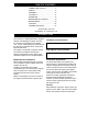
CONTROLS 6 7 1 6 5 11 9 2 4 3 7 8 10 1. 2. 3. 4. 5. 6. Throttle Control Choke Control Ignition Switch PTO Switch Service Meter Operator Presence Levers - 11 - 7. 8. 9. 10. 11.
OPERATION Steering Levers WARNING! Avoid injury. Read and understand the entire Safety section before proceeding. WARNING! Avoid injury! When the engine is running and the shift lever is engaged, releasing only one steering latch causes the unit to circle around one drive wheel. ALWAYS hold both steering levers against the handlebar when releasing the steering lever latches. ALWAYS release levers slowly.
Throttle Control Fuel Tank The throttle lever changes the speed of the engine. Move the throttle lever to FAST (rabbit) to increase engine speed. Move the lever to SLOW (turtle) to decrease engine speed. Use regular grade unleaded fuel with an octane rating of 87 octane or higher. Fuel blends containing up to 10% ethanol or up to 15% MTBE reformulated fuel are acceptable. Do not use fuel or additives containing methanol as engine damage can occur.
Emergency Stops Operating the Unit 1. 2. 3. 4. Use the unit only in the operator’s position directly behind the controls. Release operator presence control(s). Turn the ignition key Off. Allow engine to stop completely. Lock steering levers in neutral. Shifting Stop unit movement by pulling both steering levers all the way up. Starting And Shut Off Before each use check the Maintenance Schedule. NOTE: The engine will not start unless the shift lever is in neutral, and the PTO is OFF. Recoil Start 1.
Operation 6. 1. 2. Start the engine. Move the throttle lever to the FAST position. 3. Engage the operator presence control and move shift lever to desired direction and speed. 4. Hold steering levers against the handlebar and release steering lever latches. 5. Hold steering levers in neutral and release steering latch levers. • To move straight forward; slowly release both steering levers to the full outward position. To move in reverse: • Hold the steering levers against the handlebar.
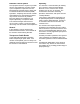
Cutting Height Adjustment ½" Spacers WARNING! ALWAYS block wheels, engage parking brake and know all jack stands are strong, secure and able to hold weight of unit during maintenance. Bushing Pin Adjust the cutting height using a combination of the mounting location on the deck carrier frame, spacers on the front casters and spacers between the mower blades and the deck spindles. The desired cutting height may be set by adjusting only the blade spacers and caster spacers.
Cutting Height Chart - Deck bolted to frame -top holes ¼" Blade Spacers ½" Caster Spacers In. Cm. Stored Between Spindle and Blade Below Weldment Above Weldment 1¼ 3.2 0 3 0 6 1½ 3.8 1 2 0 6 1¾ 4.4 2 1 0 6 2 5.1 3 0 0 6 1½ 3.8 0 3 1 5 1¾ 4.4 1 2 1 5 2 5.1 2 1 1 5 2¼ 5.7 3 0 1 5 1¾ 4.4 0 3 2 4 2 5.1 1 2 2 4 2¼ 5.7 2 1 2 4 2½ 6.35 3 0 2 4 2 5.1 0 3 3 3 2¼ 5.7 1 2 3 3 2½ 6.35 2 1 3 3 2¾ 7.
Parking 1. 2. 3. 4. Trailer Transporting Shut off the unit. See Shut Off and Stop Mowing. Remove the ignition key. Lock both steering lever latches in neutral to engage the brakes. Chock or block the wheels if parked on a slope. Pushing unit by hand To move the unit without the engine running: 1. Put the shift lever in neutral. 2. Disengage the lock latches. Release steering levers. The brake is disengaged when the steering levers are released. 3. Push unit to desired location.
MAINTENANCE SCHEDULE Before Use MAINTENANCE Perform the Safety Interlock System Check. 1) ● Check the engine’s oil level. Do not operate with low oil level. ■ Check/clean the engine’s air cleaner. ■ Check/clean the engine’s cooling air intake. ■ Check for fuel and oil leakages. ♦ Check all nuts, bolts, and other fasteners. Replace if needed.
MAINTENANCE If unit turns to the right: 1. Reduce the air pressure in the left tire. 2. Increase the air pressure in the right tire. 3. Check for brake binding on right wheel and adjust as needed. If unit turns to the left: 1. Reduce the air pressure in the right tire. 2. Increase the air pressure in the left tire. 3. Check for brake binding on left wheel and adjust as needed. WARNING! Avoid injury. Read and understand the entire Safety section before proceeding.
Adjusting Brakes NOTE: The traction belt must disengage as the brake starts to engage. 1. Turn off the engine, remove the ignition key and allow unit to cool. 2. If brakes do not disengage fully when traction belt is engaged, the brakes are too tight. Disconnect trunnion from the clutch weldment and turn the trunnion up the brake rod to reduce braking. Reconnect the trunnion to the clutch weldment. 10. 11. 12. 13. Replace traction belt guard. Replace clutch idler pulley spring. Lower the unit.
Adjusting Shift Lever Linkage Replacing Transmission Belt 1. IMPORTANT If the shift lever and the transmission detent are improperly aligned, the transmission may fail prematurely. Align the shift lever and detent as carefully as possible. The .030 (.8 mm) clearance helps prevent premature wear of the detent plate and shift lever. Trans Sheave Trans Belt The transmission shift lever is attached to the transmission shift arm with two 5/16-18 bolts. Adjusting: 1. Stop the engine and remove ignition key.
Belt Replacement 48" 5. Deck Belt 1. Turn off the engine, remove the ignition key and allow unit to cool. 2. Remove deck cover. 3. Turn the deck belt idler spring adjusting nut to relieve tension from the idler spring. 4. Remove deck belt from deck sheaves. 6. 7. 8. 9. Remove mower drive belt from deck sheaves and mower clutch sheave. Install new mower drive belt on deck sheaves and mower clutch sheave. Tighten the adjusting nut to tension the belt.
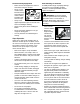
Replacing Mower Spindle Bearings Blade Sharpening 1. Discard mower blade if: • More than ½" (1.27 cm) of metal is removed. • Air lifts become eroded. • Blade is bent or broken. 2. Sharpen mower blade by removing an equal amount of material from each end of mower blade. DO NOT change angle of cutting edge or round the corner of the mower blade. 1. 2. 3. 4. 5. 6. 7. Incorrect filing profile Turn the engine off. Remove the ignition key. Remove the ignition wire from the spark plugs. Remove mower blade.
Replacing Caster Pivot Bearing Bushings 1. 2. 3. 4. 5. Electrical Service Replacing Fuse Turn the engine off. Remove the ignition key. Remove the ignition wire from the spark plugs. Raise and securely support the front of the mower deck. Remove lynch pin, spacer bushings, washer and caster yoke and wheel assembly. Remove and discard upper and lower bushings. Install new bushings. IMPORTANT Do not allow washer to sit on caster yoke. It must be on top of the height-of-cut spacer bushings 6. 7.
STORAGE WARNING! Avoid injury. Read and understand the entire Safety section before proceeding. Storage for Two Months or More 1. Check each item in the Maintenance Schedule, but do not add gasoline. 2. Clean the unit. Touch up all scratched painted surfaces. IMPORTANT Never spray unit with high pressure water or store unit outdoors. Store unit in a cool, dry, protected location. 3. 4. Clean unit thoroughly with mild soap and low pressure water and lubricate (see General Lubrication).
TROUBLESHOOTING Problem Engine will not start Probable Cause Correction Safety Interlock System is preventing start Make sure the shift lever is in neutral, the ignition key is in the ON position, and the Power Take Off is OFF Fuel tank empty or fuel is contaminated Add fuel or replace with clean, fresh fuel Air cleaner is clogged or damaged. Clean or replace the filter element see engine manual Safety Interlock System out of adjustment or defective.
SPECIFICATIONS Model Number Model W436 W448 967334301-00 967334401-00 Engine Brand Briggs & Stratton Engine Model Vanguard 3567 18 HP Governed RPM (May be different from maximum RPM) 3600±100 Cooling Capacity Air cooled Speed Forward Maximum – mph (km/h) 5.4 (8.7) Reverse Maximum – mph (km/h) Reverse Assist Turning Radius 0 Brakes 6-Inch Band Electrical Starter Recoil Power Take-Off Electric PTO Clutch Fuel Fuel Type Refer to engine manual Tank Capacity – gal. (L) 5.
www.husqvarna.