January 2006 INSTALLATION & SERVICE INSTRUCTIONS FOR DCCG and DCSG (-D) MODELS Dipping and Display Case First Call for help (US and Canada): 1-800-922-1919 Soporte Tècnico y Asistencia (Mèxico): 01-800-522-1900 For a Service Network Locator and other Information visit us at www.hussmann.
TABLE OF CONTENTS Introduction Inspection 3 3 Specifications Construction Cabinet Dimensions Cabinet Capacities Electrical Data 3 4 4 4 Installation and Start Up 5 Location Power Requirements Start Up Procedures 5 5 5 Operation and Maintenance Temperature Control Display Lighting Anti-sweat Heaters Defrosting Condensing Unit Cleaning the Condenser Cleaning Exterior Cleaning Interior Serial Plate Location and Refrigerant Charges Temperature Control Replacement 6 6 6 6 7 7 7 7 7 7 Operational Data
TABLE OF CONTENTS CON’T Dipping Using Guide Loading Storage Lids Temperature Control Load Limits Dipping 10 10 10 10 - 11 11 11 Maintenance Warranty and Parts Information 11 12 - 13 2
INTRODUCTION, INSPECTION, SPECIFICATIONS INSTALLATION and START UP INTRODUCTION – durability. The entire assembly is then chemically treated and finished with baked-on powder paint. The liner is an all welded assembly of electro zinc steel. Copper evaporator tubing is fastened to the liner and applying a conductive material on both top and bottom of the tubing further enhances maximum heat transfer. The liner is also chemically treated and painted with baked-on powder paint.
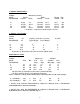
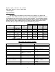
CABINET DIMENSIONS – Cabinet Model DCSG/DCCG -4 -8 -12 -16 Dimensions (inches) Length Width Outside Inside Outside * Inside 25 3/8 21 47 7/16 43 1/8 67 5/16 63 87 7/16 83 1/8 * -D models Height Ship Outside Wt. 25 13/16 21 ½ 51 ¼ 25 13/16 21 1/2 51 1/4 25 13/16 21 1/2 51 1/4 25 13/16 21 1/2 51 1/4 (with doors) outside width = 27 9/16 260 405 515 625 CABINET CAPACITIES – Cabinet Model DCSG/DCCG -4 -8 -12 -16 Cu. Ft. Capacity (9 1/2 dia. 3 gal cans) Upper Display Lower Display 3.3 4 8.9 8 4 14.
equipment on the same circuit. Use a time delay fuse or circuit breaker. The supply circuit must be properly grounded and conform to National and Local Electrical Codes. Voltage, as measured at the compressor terminals during operation, must not vary more than 5% from cabinet serial plate rating. If a low voltage condition exists, contact your electrician or power company. INSTALLATION and START UP LOCATION – The location of your cabinet is important.
OPERATION AND MAINTENANCE SERVICING DATA AND PROCEDURES OPERATION and MAINTENANCE • Raise top and canopy as an assembly and place wood spacers between top and cabinet. • Remove frame. • Disconnect spade terminal splices and remove. • Reassemble reverse order – resistance heater wire must be taped back into position TEMPERATURE CONTROL – The thermostat, which senses the cold wall temperature, is located at the lower rear right corner of the cabinet through the access panel.
be taken not to puncture the interior walls or remove paint from the walls during this procedure. CLEANING EXTERIOR / INTERIOR – When cleaning the exterior of the cabinet use a soft cloth or sponge with water and mild detergent. Rinse and wipe dry. Be sure to disconnect power from the cabinet prior to starting defrost operation.
Replace spade connectors and reinstall dial plate and two screws which hold control in place. Operational Data The following operational data is based on lab tests, and may vary under field conditions. The conditions shown at the non-recommended high 85°F ambient are shown for information only and a possible reason for jobsite problems.
4. Restriction pinched cap tube 5. Restriction moisture 6. Inadequate air over condenser 7. Defective condenser fan motor TROUBLE High head pressure Warm storage temperatures PROBABLE CAUSE SOLUTION 1. Relocated cabinet 2. Clean condenser or remove air flow restriction 3. Replace motor 1. Temperature control not set properly 2. Short of refrigerant 1. Reset control 4. Leak check, change drier, evacuate and recharge 6. Heavy frost on side walls 2. Leak check, change drier, evacuate and recharge 3.
DIPPING USERS GUIDE The general success of any ice cream dipping department depends to a great extent on the people within that department. If at all possible, a single individual should be assigned the direct responsibility of assuring that proper operational procedures are being followed. LOADING – Careful thought should be given to the placement of flavors within the cabinet prior to the opening of the dipping department.
TEMPERATURE CONTROL – The temperature control is factory set for normal dipping temperatures. If, after a week or so of operation, it is decided that a higher or lower temperature is required, only a qualified refrigeration mechanic should adjust the control. Other than the initial adjustment and possibly a seasonal adjustment, no other setting should be required. If the cabinet temperature fluctuates to any great extent, a refrigeration mechanic should be notified.
W ARRA NT Y – Please read carefully to assure prompt and accurate service Ordering Replacement Parts – • • • Contact your nearest Hussmann Distributor. Always specify model and serial number of cabinet. If correct part number is not known, give a clear description of part itself and its function in the cabinet. Warranty Parts Procedure – • Same as items above • Give original installation date of cabinet and, if possible, forward a copy of the original invoice or delivery receipt.
BLUE LAMP BLUE LIGHT SWITCH WHT BLK RED BALLAST RED CANOPY HEATER WHT 26 28 6 23 25 31 27 29 5 BLK HIGH LIMIT SWITCH TEMPERATURE CONTROL BLK BLK 22 24 30 COMPRESSOR MOTOR OVERLOAD TERMINAL BLOCK C R S RELAY POWER CORD 115 VOLT 60 Hz 1 Ph BLK POWER SWITCH BLK WHT GRN START CAP. CONDENSER FAN WHT 1 S 2 M COMPRESSOR REV EO # REV DATE REV BY - APPROVED BY - - - USAGE: DCCG-4 TOLERANCES UNLESS OTHERWISE SPECIFIED: FRACTIONAL 1/32" DECIMAL 0.