P/N 374511B March, 1997
P/N 374511B PROTOCOL™ Hand Held Device TABLE OF CONTENTS Key Pad Instructions . . . . . . . . . . . . . . . . . . . . . . . . . . .1 Select Equipment . . . . . . . . . . . . . . . . . . . . . . . . . . . . .3 Protocol™ Main Menus . . . . . . . . . . . . . . . . . . . . . . . .4 Status Menu . . . . . . . . . . . . . . . . . . . . . . . . . . . . . . . . .6 Configuration Menu . . . . . . . . . . . . . . . . . . . . . . . . . . .8 Defrost Menu . . . . . . . . . . . . . . . . . . . . . . . . . . . . . . .
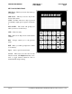
Hand Held Device PROTOCOL™ P/N 374511B Page 1 KEY PAD INSTRUCTIONS Shift Upper – This key is used to key in the top (red) letters. Shift Lower – This key is used to key in the bottom (blue) letters. NOTE: If either of the above keys is pressed accidentally, simply press it again to deactivate it. INS & DEL – The screen will prompt you when you need to use these keys. CLR – Clears last entry Help – There are no help screens on the current software. ESC – Escape; returns you to the previous menu.
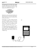
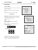
P/N 374511B Page 2 PROTOCOL™ Hand Held Device The Hussmann Interface Module may be operated from either battery power or from a 120V/12VDC transformer. When using the transformer, connect Module before plugging in the transformer. The startup screen will automatically appear. HUSSMANN INTERFACE MODULE (C) 1991 HUSSMANN CORPORATION VER 1.30 When battery operated, the Module will shut down if the key pad has not been used for three minutes.
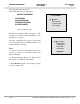
Hand Held Device P/N 374511B PROTOCOL™ Page 3 Following the startup screen, the SELECT EQUIPMENT screen will appear. SELECT EQUIPMENT 1-PROTOCOL 2-CASE CONTROL 3-PUMPING STATION 4-FLUID COOLER SELECT EQUIPMENT 1-PROTOCOL 2-CASE CONTROL 3-PUMPING STATION 4-FLUID COOLER Press 1 on the key pad. The PROTOCOL™ MAIN MENU will appear. This screen has 5 submenus each of which has its own submenu(s), see page 4.
P/N 374511B PROTOCOL™ Page 4 Hand Held Device PROTOCOL MAIN MENU (_ _) = PAGE NUMBERFORMORE INFORMATION 1- STATUS MENU (07) 2- CONFIG MENU (10) CONFIG MENU 3- DEFROST MENU (23) DEFROST MENU 4- MAINT MENU (28) MAINT MENU 1-SET THE CLOCK (10) 5- ALARM MENU (30) 1-VIEW/SET ITEMS (23) 2-SENSOR SETUP (11) 1-FORCE A COMP ON 2-COPY SCHEDULE (25) 3-PROTOCOLSETUP(15) ALARM MENU 2-CLEAR FORCE FLAG 3-ASSIGN OUTPUTS (26) 4-COMM SETUP (20) 3-FORCE A COMP OFF *4-ASSIGN CIRCUITS 5-LIGHTCONTROL(21) A01- LO SUCTION PRES
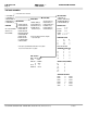
Hand Held Device P/N 374511B PROTOCOL™ Page 5 CONFIG MENU (_ _) = PAGENUMBER FORMORE INFORMATION 1- SET THE CLOCK (10) 2- SENSOR SETUP (11) 3- PROTO C O LS E T U P( 1 5 ) 4- COMM SETUP (20) COMM SETUP MENU 5- LIGHT CONTROL(21) 6-TEMPCONTROL(22) STATION NUMBER - 99 BAUD RATE - 19200 TEMPERATURE CONTROL 1-REFR CIRCUIT #1 (22) 2-REFR CIRCUIT #2 (22) 3-REFR CIRCUIT #3 (22) 4-REFR CIRCUIT #4 (22) 5-REFR CIRCUIT #5 (22) 6-REFR CIRCUIT #6 (22) 7-REFR CIRCUIT #7 (22) 8-REFR CIRCUIT #8 (22) REFR CIRCUIT #1 T E M
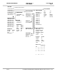
P/N 374511B Hand Held Device PROTOCOL™ Page 6 DEFROST MENU (_ _) = PAGENUMBER FORMOREINFORMATION 1- VIEW/SET ITEMS (23) 2- COPY SCHEDULE (25) 3- ASSIGN OUTPUTS (26) DEFROST BOARD #1 *4-ASSIGN CIRCUITS OUTPUT CIRCUIT FOR SPLIT S U C T( 2 7 ) 1 1 2 2 SUCTION ASSIGNMENT (27) 3 3 CIRCUIT SUCTION 4 4 1 01 2 01 DEFROST BOARD #2 3 01 OUTPUT CIRCUIT 4 01 5 5 5 01 6 6 6 01 7 7 7 01 8 8 8 01 EXPANSION BOARD OUTPUT CIRCUIT 9 00 10 00 11 00 12 00 EXPANSION BOARD OUTPUT CIRCUIT 13 00 14 00 15 00 16 00 DEFROST MENU
Hand Held Device P/N 374511B PROTOCOL™ Page 7 STATUS MENU 1-STATUS MENU PROTOCOL MAIN MENU This is a read only menu. It gives you current operating conditions. 1-STATUS MENU 2-CONFIG MENU P1 gives the present pressure for the suction manifold. 3-DEFROST MENU P2 gives the second suction pressure input.* 5-ALARM MENU 4-MAINT MENU Press ESC Key. SETPOINT is the Suction Set Point for the control board. The board turns compressors ON and OFF to maintain this suction pressure.
P/N 374511B Page 8 Hand Held Device PROTOCOL™ STATUS MENU (Continued) 2-DEFROST / TEMP CKT This is a read-only menu. This screen shows the current operational status of Defrost Circuits and associated temperatures as provided by Auxiliary inputs. STATUS MENU 1-PRESSURES 2-DEFROST / TEMP CKT NAME gives a description of the case loads for this defrost circuit.
Hand Held Device P/N 374511B PROTOCOL™ Page 9 STATUS MENU (Continued) 3-TEMPERATURE MENU TEMPERATURE MENU T1 temperature reading for suction pressure reset or optional temperature input. T2 temperature reading for satellite or optional temperature input. F SP T1 - - 40 0 T2 - - 40 0 T3 - - 40 0 PRESS ENT FOR MORE T3 If split suction is installed, T3 may be factory set to read head pressure instead of temperature. Screen will show T3- ___PSI.
P/N 374511B Hand Held Device PROTOCOL™ Page 10 CONFIG MENU 2-CONFIG MENU PROTOCOL MAIN MENU This set of menus is used to make changes in the Protocol’s configuration. Press 2 on the Keypad to enter the CONFIG submenu. 1-STATUS MENU 2-CONFIG MENU 3-DEFROST MENU 4-MAINT MENU 5-ALARM MENU 1- SET THE CLOCK Press 1 on the Keypad to enter the CLOCK SETUP submenu. This screen has 5 fields used to set the correct time/date.
Hand Held Device P/N 374511B PROTOCOL™ Page 11 CONFIG MENU (continued) CONFIG MENU 2- SENSOR SETUP 1-SET THE CLOCK Press 2 on the Keypad to enter the Sensor Setup Submenu. This screen has 6 menus. 2-SENSOR SETUP 3-PROTOCOL SETUP 4-COMM SETUP 1- PRESSURE #1 5-LIGHT CONTROL Press 1 on the Keypad to enter the Pressure #1 Submenu. PRESSURE #1 controls the suction pressure for the Protocol Control. Press the CLR key. Key in the applicable suction pressure in psig for HI ALARM and press ENT.
P/N 374511B Page 12 Hand Held Device PROTOCOL™ CONFIG MENU (continued) 2- PRESSURE #2 Press 2 on the Keypad to enter the Pressure #2 Submenu. PRESSURE #2 controls the suction pressure or Split Suction on the Protocol Control. Press the CLR key. Key in the applicable suction pressure in psig for HI ALARM and press ENT. Repeat for LO ALARM.
Hand Held Device P/N 374511B PROTOCOL™ Page 13 CONFIG MENU (continued) 3- TEMP #1 SENSOR SETUP MENU 3 - T E M P # 1 allows you to establish set point and alarm levels for the first temperature input. Press 3 on the Keypad to enter the Submenu. TEMP 1-PRESSURE #1 2-PRESSURE #2 3-TEMP #1 #1 4-TEMP #2 5-TEMP #3 The ALM DELAY is a programmable time delay. This sets the time it will take before the control log’s the alarm.
P/N 374511B Hand Held Device PROTOCOL™ Page 14 CONFIG MENU (continued) SENSOR SETUP MENU 1-TEMP #4 6- AUX SENSORS 2-TEMP #5 Press 6 on the Keypad to enter the Auxiliary Sensors Submenu. 3-TEMP #6 4-TEMP #7 5-TEMP #8 6-AUX SENSORS AUXILIARY SENSORS provide six temperature inputs—analog or digital. AUXILIARY SENSORS Analog for thermistors Digital for thermostats. 1-AUX SENSOR #1 2-AUX SENSOR #2 ANALOG SETTING ANALOG accommodates temperature readings between – 40 and + 120˚F.
Hand Held Device P/N 374511B PROTOCOL™ Page 15 CONFIG MENU (continued) CONFIG MENU 3- PROTOCOL SETUP Press 3 on the Keypad to enter the Protocol Setup Submenu. 2-SENSOR SETUP 1- REFR SETUP 3-PROTOCOL SETUP 1-SET THE CLOCK 4-COMM SETUP Press 1 on the Keypad to enter the REFR SETUP submenu.
P/N 374511B Page 16 Hand Held Device PROTOCOL™ CONFIG MENU (continued) MixMatch compressor cycling is used when compressors of varying horsepowers have been installed. This algorithm allows the compressor horse power to be more closely matched with the evaporator load There are 16 available steps for MixMatch cycling. The additional steps are accessible by pressing the arrow to view additional screens.
Hand Held Device P/N 374511B PROTOCOL™ Page 17 CONFIG MENU (continued) MIXMATCH PROGRAMMING EXAMPLE 1. Start by making a column for each compressor. 2. The first row must be all 0’s. 3. Each row will be a step. Each step should increase rack capacity by the smallest increase in capacity possible. 4. Use an X in the column for a compressor being on, and a 0 in the column for a compressor being off. It may help to write the capacity in horsepower to the right of each row. 5.
P/N 374511B Page 18 Hand Held Device PROTOCOL™ CONFIG MENU (continued) 2- DEFR SETUP PROTOCOL SETUP Press 2 on the Keypad to enter the Defrost Setup Submenu. 1-REFR SETUP 2-DEFR SETUP This screen programs the Control Board for the defrost parameters: 3-DESCRIPTION 4-ALARM OUTPUT Number of defrost circuits controlled Interlock status— ENABLED/DISABLED To change numeric fields, press the CLR key. Key in the applicable number. Press ENT. Use the key, toggle between ENABLED/DISABLED. Press ENT.
Hand Held Device P/N 374511B PROTOCOL™ Page 19 CONFIG MENU (continued) PROTOCOL SETUP 3- DESCRIPTION 1-REFR SETUP Press 3 on the Keypad to enter the Description Submenu. This screen provides for a 16 character description of the Protocol unit for user identification on Hussnet™. 2-DEFR SETUP 3-DESCRIPTION 4-ALARM OUTPUT Press the CLR key. Key in the description . Press Shift Upper to use the red (upper) letters and Shift Lower to use the blue (lower) letters.
P/N 374511B Page 20 Hand Held Device PROTOCOL™ CONFIG MENU (continued) CONFIG MENU 1-SET THE CLOCK 2-SENSOR SETUP 4- COMM SETUP 3-PROTOCOL SETUP Press 4 on the Keypad to enter the Communication Setup Submenu. 5-LIGHT CONTROL 4-COMM SETUP 6-TEMP CONTROL This screen provides for assigning each Protocol a station number for computer identification on Hussnet™. It also provides baud rate assignment. The baud rate is the rate at which a computer can receive data from Protocol.
Hand Held Device P/N 374511B PROTOCOL™ Page 21 CONFIG MENU (continued) CONFIG MENU 5- LIGHT CONTROL 1-SET THE CLOCK Press 5 on the Keypad to enter the Light Control Submenu. 2-SENSOR SETUP 3-PROTOCOL SETUP 4-COMM SETUP 1-CIRCUIT #1 5-LIGHT CONTROL Press 1 or 2 on the Keypad to enter the Circuit # Submenu. This screen programs lighting controls on one circuit. Use the key to toggle between ENABLED / DISABLED to activate the lighting function. Press ENT.
P/N 374511B Page 22 Hand Held Device PROTOCOL™ CONFIG MENU (continued) CONFIG MENU 6- TEMPERATURE CONTROL Press 6 on the Keypad to enter the Temperature Control Submenu. Note: Temperature Control is available on HAND HELD DEVICE V2.40 or greater. 1-SET THE CLOCK 2-SENSOR SETUP 3-PROTOCOL SETUP 4-COMM SETUP 5-LIGHT CONTROL 6-TEMP CONTROL Press the number of the Temp Refr Circuit you wish to view or use the and to move to the appropriate entry and press ENT.
Hand Held Device P/N 374511B PROTOCOL™ Page 23 DEFROST MENU PROTOCOL MAIN MENU 3-DEFROST MENU Press 3 on the Keypad to enter the Defrost submenu. 1-STATUS MENU 2-CONFIG MENU 3-DEFROST MENU 4-MAINT MENU 1- VIEW/SET ITEMS 5-ALARM MENU Press 1 on the Keypad to enter the VIEW/SET ITEMS Submenu. This screen shows three columns: DEFROST MENU CIRCUIT lists the defrost circuit within the Protocol. The numbers 1 through 8 are fixed.
P/N 374511B Page 24 Hand Held Device PROTOCOL™ DEFROST MENU (continued) WITH THE CURSOR ON A CIRCUIT NUMBER, press the ENT key to open that circuit submenu. DEFROST MENU CIRCUIT SYSTEM STATUS 5 00 N/A CIRCUIT #6 - REFR 6 00 N/A Press the CLR key. Key in the applicable Lineup name. Press ENT. Repeat for NAME, NUMBER/DAY, DEFR LENGTH and 1ST DEFR HOUR:MINUTES.
Hand Held Device P/N 374511B PROTOCOL™ Page 25 DEFROST MENU (continued) DEFROST MENU 1-VIEW/SET ITEMS 2-COPY SCHEDULE 2- COPY SCHEDULE 3-ASSIGN OUTPUTS 4-ASSIGN CIRCUITS Press 2 on the Keypad to enter the Copy Schedule Submenu. Press the CLR key. Key in the applicable Circuit # for Copy From. Press ENT. Press the CLR key. Key in the applicable Circuit # for Copy to. Press ENT. FOR SPLIT SUCT COPY DEFROST SCHEDULE COPY FROM CIRCUIT - 00 COPY TO CIRCUIT - Press ESC to return to DEFROST MENU.
P/N 374511B Hand Held Device PROTOCOL™ Page 26 DEFROST MENU (continued) DEFROST MENU 3- ASSIGN OUTPUTS 1-VIEW/SET ITEMS Press 3 on the Keypad to enter the Assign Outputs Submenu. 2-COPY SCHEDULE 3-ASSIGN OUTPUTS 4-ASSIGN CIRCUITS FOR SPLIT SUCT Press ENT to move the cursor to the value to be changed. Press the CLR key. DEFROST BOARD #1 Key in the applicable Circuit #. Press ENT.
Hand Held Device P/N 374511B PROTOCOL™ Page 27 DEFROST MENU (continued) DEFROST MENU 4- ASSIGN CIRCUITS FOR SPLIT SUCTION 1-VIEW/SET ITEMS 2-COPY SCHEDULE NOTE: This item only appears when the unit is configured for the split suction option. 3-ASSIGN OUTPUTS 4-ASSIGN CIRCUITS FOR SPLIT SUCT Press 4 on the Keypad to enter the Assign Circuits For Split Suction Submenu. Press ENT to move the cursor to the value to be changed. Press the CLR key.
P/N 374511B Page 28 Hand Held Device PROTOCOL™ MAINT MENU PROTOCOL MAIN MENU 4- MAINT MENU 1-STATUS MENU 2-CONFIG MENU Press 4 on the Keypad to enter the Maintenance Menu Submenu. This screen has one function, four menus, and a second page. 3-DEFROST MENU 4-MAINT MENU 5-ALARM MENU The functions is: 2-CLEAR FORCE FLAG MAINT MENU 1-FORCE A COMP ON Simply press 2 to activate clear function. Press Numbers 1, 3, 4, 5 on the Keypad to enter the Submenu. Key in compressor or defrost circuit #. Press ENT.
Hand Held Device P/N 374511B PROTOCOL™ Page 29 4- MAINT MENU Press 4 on the Keypad to enter the Maintenance Menu Submenu. MAINT MENU 6-CLEAR RUN METER 7-FORCE LIGHT ON Press ENT to move to the second page. This screen has two functions and three menus. 8-FORCE LIGHT OFF 9-CLEAR ALM TABLE 0-RESET CONTROL The two functions are: 6-CLEAR RUN METER 9-CLEAR ALARM TABLE FORCE A LIGHT ON Simply press 6 or 9 to activate clear function. Press Numbers 7, 8, 0 on the Keypad to enter the Submenu.
P/N 374511B Page 30 Hand Held Device PROTOCOL™ ALARM MENU 5-ALARM MENU PROTOCOL MAIN MENU Press 5 on the Keypad to enter the Alarm Submenu. 1-STATUS MENU 2-CONFIG MENU 3-DEFROST MENU This screen lists the last 16 alarms giving the type, time (24 hour clock) and date of each. Alarms may be continued on the next screen. To read continued alarms, Press ENT. The screen will read END OF ALARMS after last alarm reading. Press ESC to return to MAIN MENU.
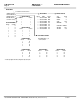
Hand Held Device P/N 374511B PROTOCOL™ Page 31 Mixmatch Programming Worksheet Compr # 1 2 3 4 5 6 HP Column Value 1 2 4 8 16 32 Total Total Column HP Value 1 2 3 4 5 6 7 8 9 10 11 12 13 14 15 16 Mixmatch Programming Worksheet Compr # HP Column Value 1 2 3 4 5 6 7 8 9 10 11 12 13 14 15 16 970307 1 2 3 4 5 6 1 2 4 8 16 32 Total HP Total Column Value HUSSMANN CORPORATION • BRIDGETON, MO 63044-2483 (Printed in U.S.A.
® CORPORATION CONDENSING UNITS AND REFRIGERATION SYSTEMS This wa r ranty is made to the original purchaser user and is N OT T R A N S F E R A B L E . ONE YEAR LIMITED WA R R A N T Y 1 . Hussmann Cor p o ration w a r rants the new Hussmann Equipment, and all parts thereof, to be free of defects in material and wo rkmanship at time of purchase. 2 .