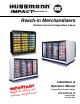
® Merchandisers Reach-in Merchandisers Medium and Low Temperature Cases NT A T R O IMP r e fo r sto n i p e e K ce! n e r e f e r f u t u re Installation & Operation Manual Shipped With Case Data Sheets P/N 0387183_D Impact Series October 2007
P/N 0387183_D iii Table of Contents INSTALLATION NSF Certification . . . . . . . . . . . . . . . . . . . . . . . . 1-1 Location . . . . . . . . . . . . . . . . . . . . . . . . . . . . . . . 1-1 Shipping Damage . . . . . . . . . . . . . . . . . . . . . . . . 1-1 Exterior Loading . . . . . . . . . . . . . . . . . . . . . . . . . 1-2 Merchandisers Shipped With End Installed . . . . 1-2 Shipping Braces . . . . . . . . . . . . . . . . . . . . . . . . . . 1-2 Remove Front Panel . . . . . . . . . . . . . . . . .
iv CONTENTS INSTALLATION TOOL LIST REVISION D — SEPTEMBER 2007 1. Added front panel text and illustration, Page 1-2. 2. Clarified shimming directions, page 1-3. 3. Added RLT information throughout. Unloading From Trailer: 4. Added note to remove bumper protective film, Page 1-6. 5. Added information on Always*Clear™ glass, page 5-1. Lever Bar (also know as a Mule, Johnson Bar, J-bar, Lever Dolly, and pry lever) Moving Dolly 6. Removed reference to Anthony doors, Page 6-5. 7.
P/N 0387183_D INSTALLATION 1-1 NSF CERTIFICATION These merchandisers are manufactured to meet ANSI / National Sanitation Foundation (NSF®) Standard #7 requirements. Proper installation is required to maintain certification. Near the serial plate, each case carries a label identifying the type of application for which the case was certified.
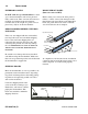
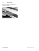
1-2 INSTALLATION EXTERIOR LOADING Do NOT walk on top of merchandisers or damage to the merchandisers and serious personal injury could occur. THEY ARE NOT STRUCTURALLY REMOVE FRONT PANEL (DOES NOT APPLY TO RLT) such as the weight of a person. Do not place heavy objects on the merchandiser. Before setting case, remove the front panel as follows: remove screws from front panel tabs, then lift the front panel. Refer to the illustration below.
P/N 0387183_D 1-3 LEVELING Merchandisers must be installed level to ensure proper operation of the refrigeration system and to ensure proper drainage of defrost water. When leveling merchandisers, use a carpenter’s level as shown. Approximately Centered Rear of Reach-in Base Component Metal leveling shims or wedges are provided with each merchandiser for use if needed. NOTE: B EGIN LINEUP LEVELING FROM THE HIGHEST POINT OF THE STORE FLOOR .
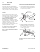
1-4 INSTALLATION DOOR ADJUSTMENT INSTALLING SPLASHGUARD BRACKETS After leveling and joining the merchandisers, adjust and level doors according to manufacturer’s instructions shipped with each product. Factory settings are lost due to vibration during shipment. 1. Attach splashguard retainer and splashguard retainer support to splashguard support bracket using two screws per bracket.
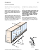
P/N 0387183_D 1-5 INSTALLING BUMPERS Offsetting the bumpers and top rails helps to disguise the joint locations, giving the lineup a smoother look. Do NOT install the last bumper sections at this time. These sections will be installed in the last step. Begin at the left end of the line-up. A starter bumper is factory-installed with end kits. Insert the internal joint trim, then add the full-length bumper.
1-6 INSTALLATION Remove protective film from bumpers once installation is complete. Optional end bumpers are factory-installed. P/N 0387183_D WWW.HUSSMANN.
P/N 0387183_D REFRIGERATION / ELECTRICAL 2-1 REFRIGERANT The correct type of refrigerant will be stamped on each merchandiser’s serial plate which is located on the left-hand end of the interior top liner. WARNING ! Refrigeration lines are under pressure and should be depressurized before attempting to make any connections. REFRIGERANT PIPING Connection Location The refrigerant line connections are at the righthand end of the merchandiser (as viewed from the front) beneath the display pans.
REFRIGERATION / ELECTRICAL 2-2 ! CAUTION The following information is applicable only for piping Hussmann merchandisers to Hussmann refrigeration equipment. Liquid Line – Off-time and Electric Defrost • May be reduced by one size after one half the case load run. Do not reduce below evaporator connection size. • Take-offs to evaporators exit the bottom of the liquid line. Provide an expansion loop for each evaporator take-off (minimum 3 in. (76 mm) diameter).
P/N 0387183_D 2-3 EXPANSION VALVE ADJUSTMENT REFRIGERATION THERMOSTAT Expansion valves must be adjusted to fully feed the evaporator. Before attempting to adjust valves, make sure the evaporator is either clear or only lightly covered with frost, and that the merchandiser is within 10 deg F (6.5 deg C) of its expected operating temperature. Adjust valves as follows: The thermostat body is located in the electrical raceway near the right-hand end of the merchandiser.
2-4 REFRIGERATION / ELECTRICAL Distributor Assembly RLT Coil TEV Bulb Mounted on Side of Suction Tube TEV Optional Gas Bypass Check Valve Heat Exchanger Assembly Component Location in RLT Models P/N 0387183_D WWW.HUSSMANN.
P/N 0387183_D 2-5 DEFROST TERMINATION THERMOSTAT The standard disc type defrost termination thermostat is not adjustable. On low-temperature merchandisers, the defrost termination thermostat or optional termination sensor is located on the right end of the coil at the bottom center return bend. If an optional adjustable thermostat is used, the bulb will be clamped to the suction line on the left end of the case.
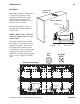
2-6 REFRIGERATION / ELECTRICAL CONTROL SETTINGS MEDIUM TEMPERATURE CONTROL SETTINGS LOW TEMPERATURE Conventional Single Compressor Measure Discharge Air Temperature at the center of the case at the discharge honeycomb. Conventional Single Compressor Measure Discharge Air Temperature at the center of the case at the discharge honeycomb. Merchandiser temperature must be controlled by a thermostat or other device with a 3–6 deg F (1.7–3.3 deg C) differential.
P/N 0387183_D 2-7 CONTROL SETTINGS MEDIUM TEMPERATURE CONTROL SETTINGS LOW TEMPERATURE Parallel Compressor Rack Measure Discharge Air Temperature at the center of the case at the discharge honeycomb. Parallel Compressor Rack Measure Discharge Air Temperature at the center of the case at the discharge honeycomb. Merchandiser temperature must be controlled by a mechanical or electronic pressure regulator or thermostat that will be mounted on the rack.
2-8 REFRIGERATION / ELECTRICAL MERCHANDISER ELECTRICAL DATA Merchandiser data sheets for specific models are shipped with this manual. The data sheets provide merchandiser electrical data, standard electrical schematics, parts lists and performance data. Refer to the merchandiser data sheets and case serial plate for electrical information. Refer to the separate wiring diagrams shipped with the case for specific information about the case and any optional wiring kits that may have been applied.
P/N 0387183_D DRIP PIPING AND SPLASHGUARDS 3-1 WASTE OUTLET AND WATER SEAL The waste outlet location varies for each of the 1, 2, 3, 4, and 5 door merchandisers. Drip piping is located between the front case base and the splashguard fixture and runs parallel to the case (see Data Sheet for exact locations). CAUTION Splashguard brackets MUST be installed before piping case. (See Page 1-3) 4. Avoid long runs of drip piping. Long runs make it impossible to provide the pitch necessary for good drainage.
DRIP PIPING 3-2 AND SPLASHGUARDS INSTALLING SPLASHGUARDS The splashguard is shipped inside each merchandiser. AFTER merchandisers have been leveled and joined, and all drip piping, electrical and refrigeration work has been completed, re-install the front color panel, then install the splashguards. First, position top of splashguard over the top edge of the bracket; second, push the lower edge of the splashguard toward the bottom of the bracket until it snaps into place.
P/N 0387183_D SEALING SPLASHGUARD TO FLOOR IF REQUIRED by local sanitation codes, or if desired by the customer, plastic splashguards may be sealed to the floor using silicone type sealer. The amount needed will depend on how much the floor is out of level. • Remove all dirt, wax and grease from the area of the splashguard where adhesion will be necessary. This is to ensure a good and secure installation. • Apply a good silicone type sealer along the bottom of the splashguard.
3-4 DRIP PIPING AND SPLASHGUARDS NOTES P/N 0387183_D WWW.HUSSMANN.
P/N 0387183_D START UP / OPERATION 4-1 STARTUP LOAD LIMITS See the merchandiser's Data Sheet Set for refrigerant settings and defrost requirements. Bring merchandisers down to the operating temperatures listed on the data sheet. Shelf life of perishables will be short if load limit is violated. AT NO TIME SHOULD MERCHANDISERS BE STOCKED BEYOND THE LOAD LIMITS INDICATED. DO NOT BLOCK HONEYCOMB.
4-2 START UP / OPERATION RLN or RMN Load Limits FAN RLNI Load Limits COIL FAN COIL RLNI Load Limits COIL FAN INSTALLING FDA/NSF REQUIRED THERMOMETER The following pages provide the same information that ships with the thermometer. This requirement does not apply to display refrigerators intended for bulk produce (refer to page 1-1). RLT Load Limits Please note that the tape cannot be exposed after installation. C O I L FAN P/N 0387183_D WWW.HUSSMANN.
P/N 0387183_D 4-3 This is an NSF-7 & US FDA Food Code Required Thermometer Suggested Mounting Locations in Single Deck Glass Front Impact Merchandisers Package Guard, Facing Out Thermometer — Hussmann Part TM.4911251 Hussmann Corporation • 12999 St. Charles Rock Road • Bridgeton, MO 63044-2483 U.S. & Canada 1-800-922-1919 • Mexico 1-800-522-1900 • www.hussmann.
4-4 START UP / OPERATION Important – Please read! This thermometer is provided in response to United States Food and Drug Administration (US FDA) Food Code [ http://www.fda.gov/ ] and National Sanitation Foundation (NSF / ANSI) Standard 7 [ http://www.nsf.org/ ] Each installation will be different The thermometer may need to be depending on how the unit is moved several times to find the stocked, shopping patterns in the warmest location.
P/N 0501904_A MAINTENANCE 5-1 CARE AND CLEANING Long life and satisfactory performance of any equipment is dependent upon the care it receives. To ensure long life, proper sanitation and minimum maintenance costs, these merchandisers should be thoroughly cleaned, all debris removed and the interiors washed down, weekly. Fan Plenum To facilitate cleaning, the fan plenum is hinged and also fastened with screws at each end.
MAINTENANCE 5-2 CLEANING HONEYCOMB ASSEMBLIES CLEANING UNDER MERCHANDISERS Honeycombs should be cleaned every six months. Dirty honeycombs will cause merchandisers to perform poorly. The honeycombs may be cleaned with a vacuum cleaner. Soap and water may be used if all water is removed from the honeycomb cells before reassembling. Be careful not to damage the honeycombs. Remove splashguards not sealed to floor.
P/N 0387183_D SERVICE 6-1 REPLACING FAN MOTORS AND BLADES See cross section for location of evaporator fans. Should it ever be necessary to service or replace the fan motors or blades be certain that the fan blades are re-installed correctly. For access to RL / RM / RLN / RMN / RLNI / RLNIE fans: ! WARNING Always disconnect the electrical power at the main disconnect when servicing or replacing any electrical component.
6-2 SERVICE RLT ONLY For access to these fans: Motor Lock Nut Tool 1. Turn off power. 2. Remove bottom display pans. Nut 3. Disconnect fan from wiring harness. 4. Remove fan blade. Fan Blade 5. Lift fan plenum and remove screws holding bottom of motor to fan basket. Gasket 6. Replace fan motor and blade. 7. Lower fan plenum. 8. Reconnect fan to wiring harness. Screws 9. Turn on power. Tape 10. Verify that motor is working and blade is turning in the correct direction. 11.
P/N 0387183_D 6-3 REPLACING ELECTRIC DEFROST HEATERS (RL / RLN / RLNI / RLNIE Only) Electric defrost requires a heater on the front and rear of the coil as shown. The heaters are held in place by tabs in the coil brackets. Electric Defrost Bend Tabs on Each Bracket to Release or Secure Heaters 9. Verify that heater is working correctly. 10. Close air gaps under fan plenum. Warmer air moving into refrigerated air reduces effective cooling.
6-4 SERVICE REPLACING ELECTRIC DEFROST HEATERS (RLT Only) RLT electric defrost heaters are located under the coil as shown in the photo below. Mounting brackets and supports are attached to plenum brackets. 1. Disconnect Power. 2. Remove lower back panels to access the heater. 3. Lift fan plenum up and back to access the heater. 4. Remove heater from bracket. 5. Position new heater in bracket. RLT Defrost Heater Location 6. Close the bracket with the element support 7. Turn on power. 8.
P/N 0387183_D 6-5 REPLACING DRAIN PAN HEATER — ELECTRIC AND GAS DEFROST (Low Temperature Only ) ! The drain pan heater is located as shown below. WARNING Always disconnect the electrical power at the main disconnect when servicing or replacing any electrical component. This includes, but is not limited to, such items as fans, heaters, thermostats and lights. Remove Drain Pan Heater 1. Disconnect power. 2. Pull heater out from under jiffy clips. 3. Position new heater under jiffy clips.
SERVICE 6-6 RLT with GAS DEFROST ONLY: REPLACING SECONDARY PLATE HEATER The secondary plate heater is located as shown below. Remove Secondary Plate Heater 1. Disconnect power. Slide Rod Heater Under Tabs. Lightly Press Down on Tabs. 2. Pull heater out from under jiffy clips. 3. Position new heater under jiffy clips. Be sure offset is properly positioned around the drain. If jiffy clips are removed, make certain sealer is replaced. 4. Reconnect power. 5. Verify that heater is working correctly.
P/N 0387183_D 6-7 REPLACING LAMP BALLAST (OTHER THAN RLT MODELS) The lamp ballasts are located in the electrical raceway, in the left-hand end of the merchandiser. To gain access: 1. Disconnect the electrical power to the light fixture. 2. Remove the front panel. A. Pull off the bumper. B. Remove screws from bumper retainer. NOTE: The front panel is attached by (2) screws (two-door), (3) screws (three -door), (4) screws (four-door), (5) screws (five door), to the front panel C.
6-8 SERVICE REPLACING RLT LAMP BALLAST The lamp ballasts are located in the electrical raceway, in the left-hand end of the merchandiser. To gain access: 1. Disconnect the electrical power to the light fixture. 2. Remove the front panel. Lift the front panel up and out from the front of the case. 3. Service or replace ballasts as required. 4. Reinstall front panel 5. Restore power to merchandiser.
P/N 0387183_D 6-9 SERVICING VERTICAL LIGHTING REPLACING DAMAGED DRAIN FITTING Refer to door manufacturer’s manual for servicing of vertical lamps. The following procedure is for the field repair of a broken drain fitting. SERVICING DOORS AND FRAMES See door manufacturer’s service manual for servicing information. One manual is shipped with each merchandiser. 1. Use a drill with a 17/8-inch (48 mm) hole saw to drill out the bottom of the drain fitting.
6-10 SERVICE REPAIRING ALUMINUM COIL The aluminum coils used in Hussmann merchandisers may be easily repaired in the field. Materials are available from local refrigeration wholesalers. Technique: 1. Locate Leak. 2. REMOVE ALL PRESSURE. Hussmann recommends the following solders and technique: 3. Brush area UNDER HEAT. 4. Use PRESTOLITE TORCH ONLY. Number 6 tip. Solders Aladdin Welding Products Inc. P.O. Box 7188 1300 Burton St.
® To obtain warranty information or other support, contact your Hussmann representative. Please include the model and serial number of the product. Hussmann Corporation, Corporate Headquarters: Bridgeton, Missouri, U.S.A.