
Lawn Mower User Manual


3-10 109627_0910
reverse are about a 65% of maximum forward speeds.
To stop the unit, release the pedal gradually (except on an
emergency). When released, the pedal returns to the Neutral
position automatically, stopping the unit. Sudden release can
result in an abrupt, and possibly dangerous stop.
For prolonged operation at a fixed forward speed, use the
forward travel pedal to attain the desired speed, then move the
cruise control switch to the “ON” position. Speed will remain
at the set value when the pedal is released.
To cancel the speed setting or stop, push the switch to the
“OFF” position or firmly depress the master brake pedal.
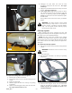
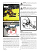
Automatic or Locked All Wheel Drive (AWD)
The transmission selector lever is used to select Automatic
Four-Wheel Drive or Locked Four-Wheel Drive.
When the Transmission Selector lever is located in the
inside slot, the tractor will run in Automatic AWD mode.
Figure 3-9
When the lever is placed in the outer slot, the mower will
run in Locked AWD mode and low range. Figure 3-10
When in motion, always bring the unit to a complete stop
before moving the transmission selector lever.
Automatic All Wheel Drive (AWD) means that the four-
wheel drive line is engaged automatically when the front
wheels start to slip, but, in normal operation, reverts to 2WD,
this provides sharp and smooth turns without damaging turf.
Locked Four-Wheel Drive should be used when additional
traction is required while operating in loose soil, wet, slippery
conditions or slopes.
NOTE: The steering (rear) axle is not powered in reverse
when tractor is operating in Automatic AWD.
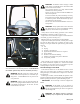
Power take-off operation
The power take-off (PTO) transfers engine power directly
to the PTO equipment.
PTO is controlled through the PTO lever. To engage the
PTO, push the lever forward. To disengage the PTO, pull the
lever rearward. Figure 3-11
WARNING: To avoid personal injury, keep chil-
dren and others away when operating PTO equip-
ment.
NOTE: The PTO lever must be placed in the disengaged
position to start the tractor.
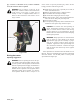
Operating the differential lock
Do not engage the differential lock when ground speed is
above 5 mph (8 kmh). Figure 3-7
The differential lock is engaged by depressing the
differential lock pedal. Depressing the pedal locks both
differential gears together, preventing one wheel from rotating
independently of the other. The lock should be used to obtain
additional traction from the opposite wheel whenever one
wheel begins to slip in wet or loose soil.
NOTE: The differential lock pedal only locks the front
axle when applied. The rear axle is not lockable.
WARNING: Do not engage the differential lock
when turning the unit. If the lock is engage when
turning, a loss of steering control will result.
To operate the differential lock depress and hold down the
pedal until the lock is positively engaged. It is best to engage
the differential lock while the wheels are turning slowly to
minimize shock loads to the drive line. If a wheel spins at
high speed, as on ice, reduce engine speed to idle before
engaging the lock, or damage may occur. The differential
lock is released when the pedal releases as the loads equalizes
on both drive wheels.
NOTE: In some instances the lock may remain engaged
after the pedal is released. This may occur if one front wheel
tends to turn at a faster speed than the other. Should this hap-
pen, the lock may be disengaged by decreasing the drawbar
pull by raising or disengaging the implement so that neither
wheel tends to slip.
Operating the hydraulic lift system
The hydraulic lift system provides hydraulic power for
raising front mounted equipment whenever the engine is
running.
To raise the front mounted equipment, pull the lift control
lever rearward and hold it until the desired equipment height
is reached. Figure 3-11
To lower the equipment, push the lever forward. When
pushed all the way forward, the lever will remain in a lowered
float detent position.
IMPORTANT: Always set the lift control lever in the
float detent position when mowing.
WARNING: Make sure the area is clear of people
before raising or lowering equipment.
WARNING:
Always lower the hydraulic lift and
equipment before stopping the unit.
Weight transfer valve
The weight transfer valve is used to transfer the front
attachment weight to the tractor unit to reduce equipment
weight on turf and prevent damage and improve front drive
wheel traction. Figure 3-11
The weight transfer valve should be used according to the
following procedures;
1. With the engine running, push the hydraulic lift lever
forward to the floating position.
2. Turn the adjusting knob clockwise until the mower or
other equipment lifts off the ground.
3. Turn the adjusting knob counter-clockwise slowly until
the mower deck front gauge wheels or other equipment
just touches the ground, then turn the knob counter-
clockwise 1/4 turn more.
4. Operate the unit over uneven terrain at desired travel
speed and observe the mower deck’s front gauge
wheels. If the wheels or equipment do not follow
ground contour, the operation will be affected.
5. To correct this condition, turn the knob 1/4 turn
clockwise at a time until the mower deck’s front gauge
wheels follow the ground contour.
Auxiliary hydraulic valve kit (optional)
An Auxiliary Hydraulic Valve kit is available from your
Hustler Dealer, as an option. When using the auxiliary valve,