Hustler Diesel Z Parts Manual ••••••• Hustler Turf Equipment ••••• P.O.
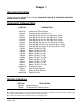
WARNING: The engine exhaust from this product contains chemicals known to the State of California to cause cancer, birth defects or other reproductive harm. IMPORTANT: This engine is not equipped with a spark arrester muffler. It is a violation of California Public Resource Code Section 4442 to use or operate this engine on any forest-covered, brush-covered, or grass-covered unimproved land. Other states or federal areas may have similar laws. This spark ignition system complies with Canadian ICES-002.
Table of Contents Chapter 1 General Information . . . . . . . . . . . . . . . . . . . . . . . . . . . . . . . . . . . . 1-1 Chapter 2 Footrest Assembly . . . . . . . . . . . . . . . . . . . . . . . . . . . . . . . . . . . . . 2-2 Rivet Nut Installation . . . . . . . . . . . . . . . . . . . . . . . . . . . . . . . . . . . . 2-4 Chapter 3 Hydraulic Component Fittings . . . . . . . . . . . . . . . . . . . . . . . . . . . . . 3-2 Hydraulic Component Mounting . . . . . . . . . . . . . . . . . . . . . . . . . . .
72" Rear Discharge Deck Pulley Assembly . . . . . . . . . . . . . . . . . . 60" Rear Discharge Deck Assembly . . . . . . . . . . . . . . . . . . . . . . . 60" Rear Discharge Deck Pulley Assembly . . . . . . . . . . . . . . . . . . 54" Rear Discharge Deck Assembly . . . . . . . . . . . . . . . . . . . . . . . 54" Rear Discharge Deck Pulley Assembly . . . . . . . . . . . . . . . . . . Spindle Assembly—796235X . . . . . . . . . . . . . . . . . . . . . . . . . . . . . Spindle Assembly—796680X . . . . . . . . .
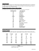
Chapter 1 General Information This Manual covers Hustler Diesel Z models 928606A/B, 928614A/B, 928622A/B, 928630A/B, 928648, 928655 & 928663. Frequently Ordered Parts PART NO. DESCRIPTION 601413X 601424 601531 601528 601466 601525 601692 601673 601691 798702 798496 794685 797696 796839 796508 600901 795633 601012 601013 130366120 785261 785279 140517020 Hydraulic Oil Filter Element Pump Drive Belt 48.50 PVL X 4 Deck Belt B-Sec 235" EL (72" Side Disch. Deck) Deck Belt B-Sec 224" EL (66" Side Disch.
Using this manual Illustrations used were current at the time of printing, but subsequent production changes may cause your machine to vary slightly in detail. Excel Industries, Inc. reserves the right to redesign and change the machine as deemed necessary, without notification. If a change has been made to your machine which is not reflected in this parts manual, see your Hustler dealer for current information and parts.
Chapter 2 Contents Footrest Assembly . . . . . . . . . . . . . . . . . . . . . . . . . . . . . . . . . . . . . . . 2-2 Rivet Nut Installation . . . . . . . . . . . . . . . . . . . . . . . . . . . . . . . . . . . . .
Footrest Assembly 1 2 3 3 4 4 5 6 7 7 9 8 7 4 4 10 4 11 1 2-2 109706 10/08
Footrest Assembly INDEX NO. SERVICE PART NO. MFG. PART NO. QTY. 1 785485 785485 2 UPPER STEP TREAD 5.00 2 785493 785493 2 LOWER STEP TREAD 9.00 3 056069 056069 2 CS .375-16X .625 HX G5 4 767954 767954 8 FW .406X .812 X.060 SAE 5 549410 109104 1 FLOOR PLATE HDZ 6 601571 601571 2 VIBRATION MOUNT 7 781880 781880 4 BUMPER .500X 1.00X .31 8 109399 109399 1 FLOOR PAN MOUNT STRAP 2 DESCRIPTION 9 086660 086660 4 NT .375-16 HXZY NL 10 054502 054502 2 NT .
Rivet Nut Installation 3 1 3 2 INDEX NO. SERVICE PART NO. MFG. PART NO. QTY.
Chapter 3 Contents Hydraulic Component Fittings . . . . . . . . . . . . . . . . . . . . . . . . . . . . . . 3-2 Hydraulic Component Mounting . . . . . . . . . . . . . . . . . . . . . . . . . . . . 3-4 Hydraulic Line Connections . . . . . . . . . . . . . . . . . . . . . . . . . . . . . . . .
Hydraulic Component Fittings 1 2 9 10 3 8 11 4 12 13 5 15 14 16 6 7 13 20 17 19 18 3-2 109706 10/08
Hydraulic Component Fittings INDEX NO. SERVICE PART NO. MFG. PART NO. QTY.
Hydraulic Component Mounting 3 TANDEM PUMPS 1 4 RESERVOIR 2 5 6 MANIFOLD 7 2 12 RIGHT WHEEL MOTOR 6 2 5 8 2 7 9 12 LEFT WHEEL MOTOR 10 4 11 5 6 3-4 109706 10/08
Hydraulic Component Mounting INDEX NO. SERVICE PART NO. 1 036236 036236 4 CS .312-18X1.000 HX G5 2 768523 768523 12 FW .343X.687X.051/.080H 3 036244 036244 2 CS .375-16X1.000 HX G5 4 767954 767954 4 FW .406X .812 X.060 SAE 5 767962 767962 10 FW .531X 1.063X.090 SAE 6 008193 008193 10 NT .500-13 HX G5 ZNYC 7 034272 034272 6 NT .312-18 HX G5 ZNYC 8 064345 064345 2 CS .312-18X2.000 HX G5 9 028274 028274 2 CB .500-13X 1.500 FULL 10 601427 601427 8 CB .
Hydraulic Line Connections 11 TANDEM PUMPS FIREWALL & OIL COOLER 12 11 10 MANIFOLD 1 3 2 9 3 9 3 RESERVOIR 10 5 4 5 LEFT WHEEL MOTOR 4 2 3 1 3 8 7 6 7 TANDEM PUMPS RIGHT WHEEL MOTOR RIGHT WHEEL MOTOR 8 13 14 15 16 LEFT WHEEL MOTOR 3-6 109706 10/08
Hydraulic Line Connections INDEX NO. SERVICE PART NO. MFG. PART NO. 1 601521 N/A 1 HOSE MANIFOLD BLOCK TO OIL COOLER 2 601583 N/A 1 HOSE MANIFOLD BLOCK 3 601001 601001 7 SPRING CLAMP .75" DIA 4 601522 N/A 1 HOSE RETURN COOLER TO MANIFOLD BLOCK 5 601584 N/A 1 HOSE MANIFOLD BLOCK 6 601617 601617 2 SPRING CLAMP 5/8" DIA.
3-8 109706 10/08
Chapter 4 Contents Deck Lift Assembly . . . . . . . . . . . . . . . . . . . . . . . . . . . . . . . . . . . . . . 4-2 Steering Sub-Assembly . . . . . . . . . . . . . . . . . . . . . . . . . . . . . . . . . . . 4-4 Steering System . . . . . . . . . . . . . . . . . . . . . . . . . . . . . . . . . . . . . . . . 4-6 Brake System . . . . . . . . . . . . . . . . . . . . . . . . . . . . . . . . . . . . . . . . . .
Deck Lift Assembly 2 1 3 4 6 5 TRACTOR FRAME 12 11 4 4 13 5 7 1 10 5 6 5 5 8 4 1 10 5 4 10 1 4 9 14 8 4 10 8 1 9 4 9 4-2 109706 10/08
Deck Lift Assembly ITEM NO. SERVICE PART NO. MFG. PART NO. QTY 1 348318 348318 1 STOP HANDLE 2 600437 600437 1 DECK HEIGHT 1/2" PIN W/A 3 783001 783001 1 DECK LIFT INDICATOR SUBASSEMBLY 4 704643 704643 8 NT .437-14 HX FLG ZN 5 781294 781294 7 CLIP E, 1.00 X .625 X .050 6 782995 782995 2 DECK LIFT SPRING SUBASSEMBLY 7 781229 781229 1 CE .750 X 2.25 X 1.75 HEADLESS 8 055749 055749 3 CS .437-14 X 1.
Steering Sub-Assembly 1 6 2 3 5 7 4 8 9 10 3 12 9 11 3 13 12 INDEX NO. SERVICE PART NO. 1 781260 N/A 2 STEERING BAR GRIP 2 109839 109839 2 HANDLE Z W/A 3 767954 767954 16 FW .406X .812 X.060 SAE 4 036244 036244 4 CS .375-16X1.000 HX G5 5 705178 705178 6 CS .375-16X1.
This page intentionally left blank.
Steering System See “Steering Sub-Assembly” on page 4-4. 2 See “Steering Sub-Assembly” on page 4-4.
Steering System ITEM NO. SERVICE PART NO. MFG. PART NO. QTY 1 348987 348987 1 2 781716 781716 2 SS .500-13X 1.750 SH ZNY 3 053199 053199 2 NT .500-13 HX JAM ZNYC 4 055822 055822 8 CS .375-16X .750 HX G5 5 767954 767954 8 FW .406X .812 X.060 SAE 6 768523 768523 16 FW .343X.687X.051/.080H 7 023655 023655 4 NT .312-24 HXZY NL 8 784439 784439 2 LOCK COLLAR 0.757 ID(FS) 9 108813 108813 1 STEER PIVOT TUBE 10 795377 795377 2 CS M 8-1.
Brake System See “Steering Sub-Assembly” on page 4-4.
Brake System ITEM NO. SERVICE PART NO. MFG. PART NO. QTY 1 782979 782979 2 2 767954 767954 4 FW .406X .812 X.060 SAE 3 023655 023655 4 NT .312-24 HXZY NL 4 768523 768523 12 FW .343X.687X.051/.080H 5 086660 086660 4 NT .375-16 HXZY NL 6 712919 712919 2 FW .406X 1.00X.12 HRD Z 7 601566 601566 2 OVERTRAVEL SPRING 8 767962 767962 2 FW .531X 1.063X.
4-10 109706 10/08
Chapter 5 Contents Engine Sub-Assembly . . . . . . . . . . . . . . . . . . . . . . . . . . . . . . . . . . . . 5-2 Belt Drive System . . . . . . . . . . . . . . . . . . . . . . . . . . . . . . . . . . . . . . . 5-6 Firewall & ROPS Assembly . . . . . . . . . . . . . . . . . . . . . . . . . . . . . . . 5-10 Air Filter Installation . . . . . . . . . . . . . . . . . . . . . . . . . . . . . . . . . . . . . 5-12 Cooling System Installation . . . . . . . . . . . . . . . . . . . . . . . . . . . . . . .
Engine Sub-Assembly 1 11 12 7 9 13 2 8 6 3 1 12 15 2 6 10 16 5 4 37 14 3 5 7 6 10 32 6 47 46 44 41 33 35 6 12 19 12 18 5 40 12 12 34 20 39 38 40 32 43 1 42 6 17 10 6 45 21 1 11 12 36 25 5 4 7 12 22 20 28 31 30 24 29 5 23 37 11 6 29 7 28 24 25 26 48 FUEL FILTER DETAIL 27 5-2 109706 10/08
Engine Sub-Assembly INDEX NO. SERVICE PART NO. 1 601355 601355 1 ENGINE, ISM S773L DIESEL 2 108976 108976 1 MOTOR MNT W/A RS, HDZ 3 601361 601361 1 MUFFLER, ISM S773L HDZ 4 601428 601428 16 CS M12-1.25 X 25 ZN 5 767962 767962 20 FW .531X 1.063X.090 SAE 6 768523 768523 16 FW .343X.687X.051/.080H 7 034272 034272 10 NT .312-18 HX G5 ZNYC 8 011510820 N/A 4 M8 X 1.25 X 20 BOLT 9 314990013 N/A 1 MUFFLER GASKET 10 036236 036236 6 CS .312-18X1.000 HX G5 NT .
NOTES: 1. Supplied with engine. 2. Torque to 33 ft-lbs. 3. Torque to 78 ft-lbs. 4. Engine oil capacity: See engine owner’s manual. 5. Engine RPM to be set at 2950±50. 6. Included in 601498 (Hydro Kit). 7. Torque to 64 ft-lbs.
This page intentionally left blank.
Belt Drive System 1 11 2 1 3 4 33 5 17 6 7 16 6 8 9 11 15 16 7 10 15 DECK BELT 11 12 14 15 5 13 15 17 29 11 17 11 22 24 34 28 23 27 3 21 20 4 30 7 19 26 18 32 25 31 2 15 5-6 109706 10/08
Belt Drive System MFG. PART NO. 601279 QTY. 1 SERVICE PART NO. 601279 1 STUB SHAFT, ISM 773 2 038836 038836 3 CS M10-1.50X25 HX ZN 3 601278 601278 1 CLUTCH, CMS250 4 767962 767962 1 FW .531X 1.063X.090 SAE 5 778217 778217 1 CS .437-20X2.250 G5 ZNY 6 601478 601478 1 BUMPER, CLUTCH MOUNT 7 768515 768515 2 FW .281X.625X.051/.080H 8 055939 055939 1 CS .250-20X .750 HX G5 9 068551 068551 1 NT .
8. For mowers with serial numbers prior to 08051277, shims are required between item 32 (pulley) and the engine. Use quantity (3) of 601662 (Arbor Shim 0.020 Thk).
This page intentionally left blank.
Firewall & ROPS Assembly FRONT OF FIREWALL DETAIL 1 20 3 2 4 5 6 2 1 3 7 1 5 10 8 12 11 9 9 13 15 9 16 17 9 12 14 4 19 19 18 19 18 5-10 109706 10/08
Firewall & ROPS Assembly INDEX NO. SERVICE PART NO. MFG. PART NO. QTY. 1 601443 601443 1 2 601470 601470 2 KNOB HAND FOR ROPS 3 601471 601471 2 LYNCH PIN W/ LANYARD 4 061812 061812 5 CS .500-13X3.500 HX G5 5 023317 023317 2 NT .500-13 UNT LK G5 ZN 2 DESCRIPTION ROPS DZ FOLDING 6 601472 601472 1 ROPS STOP 7 077859 077859 1 CS .500-13X3.250 HX G5 8 055939 055939 4 CS .250-20X .750 HX G5 9 768515 768515 16 FW .281X.625X.051/.
Air Filter Installation 2 3 4 17 18 1 5 AIR FILTER DETAIL 6 7 10 3 9 1 6 3 9 3 3 11 13 3 6 9 12 1 8 13 3 9 3 11 10 14 16 15 5-12 109706 10/08
Air Filter Installation SERVICE PART NO. MFG. PART NO. QTY. 1 782763 782763 1 DONALDSON AIR CLEANER 2 079186 079186 2 CS .312-18X1.250 HX G5 3 768523 768523 9 FW .343X.687X.051/.080H 4 785741 785741 1 BAND AIR CLEANER MOUNT 5 795138 795138 1 AIR FILTER INDICATOR 6 057661 057661 5 HOSE CLAMP 7 601359 601359 1 HOSE FRESH AIR INTK HDZ 8 601360 601360 1 HOSE INTAKE HDZ 9 034272 034272 5 NT .312-18 HX G5 ZNYC 10 016253 016253 3 CB .312-18X .
Cooling System Installation 26 13 2 11 12 8 10 2 9 11 11 22 2 13 2 13 7 12 2 21 2 RADIATOR DETAIL 11 6 3 24 5 22 20 25 4 23 21 20 2 24 1 6 6 SEE RADIATOR DETAIL FOR ASSEMBLY 13 2 1 4 2 1 17 13 15 2 14 14 18 2 19 14 2 6 16 2 13 2 1 2 13 5-14 109706 10/08
Cooling System Installation INDEX NO. SERVICE PART NO. 1 036236 036236 6 CS .312-18X1.000 HX G5 2 768523 768523 21 FW .343X.687X.051/.080H 3 109559 109559 1 INNER PANEL FENDER 4 601069 601069 4 CN .312-18X.200 MAX THK 5 794644 794644 1 GM 1.50 X 2.12 X 1.75 706531 706531 1 GM 1.12X1.75X1.37X.12 6 016253 016253 7 CB .312-18X .
Engine Cover Installation 35 5 6 1 7 35 3 2 34 8 32 3 15 2 10 9 11 14 32 12 13 15 16 33 6 12 13 4 31 28 13 30 14 29 23 26 27 24 23 7 17 18 7 25 19 21 20 22 21 5-16 109706 10/08
Engine Cover Installation INDEX NO. SERVICE PART NO. MFG. PART NO. QTY. 1 601363 601363 1 2 767954 767954 2 FW .406X .812 X.060 SAE 3 068551 068551 8 NT .250-20 HXZY NL 4 712927 712927 2 FW .344X 1.00X.12 HRD Z 5 601364 601364 2 HINGE 3"X3" ZN W/ HOLES DESCRIPTION HOOD HDZ 6 601503 601503 8 CB .250-20 X .625 ZNYC 7 768515 768515 10 FW .281X.625X.051/.080H 8 601379 601379 1 SB .375 X 1.50SH .
Fuel System 1 3 8A 2 1 8B 4 6 7A 6 4 7B 5 7B 4 2 3 4 5 7A 4 4 9 10 11 13 8A 8B 9 12 17 19 18 10 12 15 11 14 16 16 5-18 109706 10/08
Fuel System INDEX NO. SERVICE PART NO. MFG. PART NO. QTY. 1 798470 798470 2 3.5" YELLOW FUEL CAP 2 601699 601699 1 FUEL TANK LEFT SIDE HDZ 601366 601366 1 FUEL TANK LEFT SIDE HDZ 601698 601698 1 FUEL TANK RIGHT SIDE HDZ 601365 601365 1 FUEL TANK RIGHT SIDE HDZ 4 000323 000323 8 CLIP 5 601369 601369 2 FUEL LEVEL SENSOR HDZ 6 601375 601375 2 O-RING SAE-14 FUEL SENSOR 7A 015818 015818 1 FUEL LINE 24.5" (SUPPLY LINE) 015818 015818 1 FUEL LINE 31.
Battery and Electrical Connections 3 YEL/BLK 3 GRN/BLK 5 ALTERNATOR CONNECTOR 19 3 13 12 14 3 PUR 17 9 10 3 YEL/WHT 7 BLK 3 3 WHT/YEL 3 ORG/GRN 6 3 RED/BLK 16 15 4 18 POSITIVE BATT.
Battery and Electrical Connections INDEX NO. SERVICE PART NO. MFG. PART NO. QTY. 1 601291 601291 1 BATTERY GRP 45 480CCA 2 793489 793489 2 BATTERY CLAMP ROD 3 109108 109108 1 BATTERY HOLDDOWN CLAMP 4 068551 068551 2 NT .250-20 HXZY NL 5 768515 768515 2 FW .281X.625X.051/.080H 6 053678 053678 1 CS M 8-1.25X16 HX G8.8 7 029876 029876 1 LW .
Instrument Panel 7 7 6 5 8 4 9 3 10 13 11 } 12 2 1 14 15 5 THROTTLE DETAIL 34 19 20 21 27 20 35 33 37 26 27 29 28 30 22 23 16 24 25 23 33 26 17 34 30 1 31 32 27 28 18 15 37 27 16 29 1 35 31 22 22 36 FIREWALL 21 22 15A 25A FUSE SIZE & LOCATION 5-22 109706 10/08
Instrument Panel INDEX NO. SERVICE PART NO. MFG. PART NO. QTY.
Electrical Schematic—601367 5-24 109706 10/08
Chapter 6 Contents Front Wheel Assembly. . . . . . . . . . . . . . . . . . . . . . . . . . . . . . . . . . . . 6-2 Front Wheel Breakdown—747782. . . . . . . . . . . . . . . . . . . . . . . . . . . 6-4 Optional Semi-Pneumatic Tire/Wheel—789537 . . . . . . . . . . . . . . . . 6-5 Drive Wheel Assembly Installation . . . . . . . . . . . . . . . . . . . . . . . . . . 6-6 Anti-Rollover Wheel Assembly . . . . . . . . . . . . . . . . . . . . . . . . . . . . .
Front Wheel Assembly 1 2 3 3 4 TRACTOR FRAME 1 2 3 4 5 3 3 4 6 7 9 5 8 4 8 3 6 7 2 10 1 11 8 9 1 11 6-2 109706 10/08
Front Wheel Assembly INDEX NO. SERVICE PART NO. MFG. PART NO. QTY. DESCRIPTION 1 705954 705954 2 CS .500-13X1.25 HX G5 Z 2 344267 344267 2 FW .510X 2.15X.187 SPL 3 712967 712976 2 FW .531X 1.375X.125 ZNY 4 784223 784223 4 BEARING W/O COLLAR 5 387035 387035 2 SPACER, 1.07 X 1.312 X 2.793 6 045765 045765 2 FW 1.030X 1.500X.134 ZN 7 349266 349266 2 FORK 8 025296 025296 4 FW .760X 1.625X.08 ZNYC 9 041475 041475 2 CS .750-10X9.50 HXZY 10 061101 061101 2 NT .
Front Wheel Breakdown—747782 1 2 1 3 4 1 5 6 ITEM NO. SERVICE PART NO. MFG. PART NO. QTY 1 039677 N/A 2 WHEEL BEARING 2 747741 N/A 1 13 X 6.50 TIRE 3 747832 N/A 1 6 X 4.5 WHEEL 4 782771 N/A 1 BEARING SPACER 5 019521 N/A 1 TIRE VALVE 6 015511 N/A 1 GREASE FITTING 45 DEG 1/4 DESCRIPTION NOTES: 1. Inflate tire to 8-12 psi.
Optional Semi-Pneumatic Tire/Wheel—789537 2 1 3 4 1 ITEM NO. SERVICE PART NO. MFG. PART NO.
Drive Wheel Assembly Installation 1 6 2 2 3 1 4 5 ITEM NO. SERVICE PART NO. PART NO. QTY DESCRIPTION 1 601238 601238 2 WHEEL & TIRE ASSY FOR SD 60", 66" & 72" & 54" RD (QTY PER TRACTOR) 2 781245 N/A 3 796250 N/A WHEEL ASSEMBLY 12 X 8.50 FOR SD 60", 66" & 72" & 54" RD 4 019521 N/A TIRE VALVE 5 061077 061077 10 WHEEL NUT (QTY PER TRACTOR) 6 770859 N/A 10 1/2" WHEEL LUG STUD 1 782078 782078 2 2 782284 NA 3 782086 N/A WHEEL ASSEMBLY 12 X 7.
Anti-Rollover Wheel Assembly 1 3 TRACTOR FRAME 3 3 3 4 1 2 1 ITEM NO. SERVICE PART NO. MFG. PART NO. QTY 1 068239 068239 2 CS .500-13 X 4.500 HX G5 ZN 2 031997 031997 2 ANTI-SCALP WHEEL 3 767962 767962 4 FW .531 X 1.063 X .090 SAE HD ZN 4 781567 781567 2 NT .500-13 HX G8 ZY NL DESCRIPTION NOTES: 1. Do not torque, wheel must turn freely.
6-8 109706 10/08
Chapter 7 Contents 72" Side Discharge XR7 Deck Assembly . . . . . . . . . . . . . . . . . . . . . 7-2 72" Side Discharge XR7 Deck Pulley Assembly . . . . . . . . . . . . . . . . 7-4 66" Side Discharge XR7 Deck Assembly . . . . . . . . . . . . . . . . . . . . . 7-6 66" Side Discharge XR7 Deck Pulley Assembly . . . . . . . . . . . . . . . . 7-8 60" Side Discharge XR7 Deck Assembly . . . . . . . . . . . . . . . . . . . . 7-10 60" Side Discharge XR7 Deck Pulley Assembly . . . . . . . . . . . . . . .
72" Side Discharge XR7 Deck Assembly 2 5 4 6 4 1 5 9 3 12 14 4 15 16 7 3 13 4 11 8 7 5 13 9 15 4 10 1 10 13 5 11 8 4 16 4 7 12 9 10 10 8 9 17 11 11 10 8 13 11 9 9 8 7 7 10 5 4 8 7 18 7-2 109706 10/08
72" Side Discharge XR7 Deck Assembly 3 2 INDEX NO. SERVICE PART NO. MFG. PART NO. QTY 1 549170 108649 1 72" DECK WA CRATED 2 798694 798694 1 RUBBER CHUTE ASSEMBLY 3 052860 052860 8 CS .375-19 X 1.250 HX G5 ZN 4 767954 767954 26 FW .406 X .812 .060 SAE HD ZN 5 086660 086660 14 NT .375-16 HXZY NL 6 103010 103010 1 DISCHARGE CHUTE MOUNT BRACKET 7 781708 N/A 6 CS .500-13 X 4.25 HX G5 ZN 8 767962 N/A 12 FW .531 X 1.063 X .
72" Side Discharge XR7 Deck Pulley Assembly 1 4 5 6 7 8 4 9 2 6 10 11 13 3 15 15 14 14 17 2 18 16 12 72" DECK ASSY 15 20 19 16 21 16 BELT GUIDE INDEXING 16 24 22 25 23 27 30 28 30 7-4 26 27 29 1 109706 10/08
72" Side Discharge XR7 Deck Pulley Assembly ITEM NO. SERVICE PART NO. MFG. PART NO. QTY 1 601531 601531 1 B-SECTION BELT 2 797910 797910 6 CS .312-18 X 1.50 FLT SH ZNYC 3 601434 601434 2 UHMW IDLER SLIDE 4 025007 025007 1 CS .625-11 X 1.75 HX G5 ZNYC 5 347443 347443 1 DECK BELT IDLER GUIDE 6 028118 028118 3 FW .62 X 1.00X.134 ZN 7 781856 781856 1 5.
" Side Discharge XR7 Deck Assembly 7 2 5 8 4 10 13 5 4 14 9 12 4 3 14 11 4 1 3 6 9 12 1 7 12 11 8 10 11 10 9 9 7 15 8 9 11 12 11 8 9 10 7 4 10 8 7 5 8 7 16 7-6 109706 10/08
66" Side Discharge XR7 Deck Assembly 3 2 ITEM NO. SERVICE PART NO. MFG. PART NO. QTY 1 549162 108536 1 66" DECK W/A CRATED 2 798694 798694 1 RUBBER CHUTE ASSEMBLY 3 052860 052860 8 CS .375-16 X 1.250 HX G5 ZN 4 767954 767954 18 FW .406 X .812 .060 SAE HD ZN 5 086660 086660 10 NT .375-16 HXZY NL 6 103010 103010 1 DISCHARGE CHUTE MOUNT BRACKET 7 781708 N/A 6 CS .500-13 X 4.25 HX G5 ZN 8 767962 N/A 12 FW .531 X 1.063 X .
66" Side Discharge XR7 Deck Pulley Assembly 1 4 5 4 8 6 7 9 10 11 2 6 15 3 13 15 14 14 18 15 15 66" DECK ASSY 17 12 19 16 2 20 21 16 16 BELT GUIDE INDEXING 16 24 22 25 23 28 26 27 30 28 7-8 29 1 109706 10/08
66" Side Discharge XR7 Deck Pulley Assembly ITEM NO. SERVICE PART NO. MFG. PART NO. QTY 1 601528 601528 1 B-SECTION BELT 2 797910 797910 6 CS .312-18 X 1.50 FLT SH ZNYC 3 601434 601434 2 UHMW IDLER SLIDE 4 025007 025007 1 CS .625-11 X 1.75 HX G5 ZNYC 5 347443 347443 1 DECK BELT IDLER GUIDE 6 028118 028118 3 FW .62 X 1.00X.134 ZN 7 781856 781856 1 5.
60" Side Discharge XR7 Deck Assembly 2 4 5 4 6 4 8 1 3 14 4 7 9 15 16 4 13 11 3 4 5 16 10 7 14 8 12 4 1 12 5 4 12 9 10 11 11 7 13 8 4 18 14 10 12 9 8 11 4 11 8 4 14 8 10 11 5 9 10 9 7 9 7 7 17 7-10 109706 10/08
60" Side Discharge XR7 Deck Assembly ITEM NO. SERVICE PART NO. MFG. PART NO. QTY. 1 549154 108501 1 60" DECK W/A CRATED 2 798694 798694 1 RUBBER CHUTE ASSEMBLY 3 052860 052860 8 CS .375-16 X 1.25 HX G5 4 767954 767954 26 FW .406 X .812 X .060 SAE HD ZN 5 086660 086660 14 NT .375-16 HX LK NY 6 103010 103010 1 DISCHARGE CHUTE MOUNT BRACKET 7 781708 N/A 6 CS .500-13 X 4.25 HX G5 ZN 8 767962 N/A 12 FW .531 X 1.063 X .
60" Side Discharge XR7 Deck Pulley Assembly 1 4 5 4 6 8 7 9 2 10 6 3 11 13 15 14 14 13 16 15 15 14 17 2 12 18 19 60" DECK ASSY 15 16 21 20 16 27 BELT GUIDE INDEXING 16 24 22 23 28 25 3 26 30 27 1 7-12 29 109706 10/08
60" Side Discharge XR7 Deck Pulley Assembly 5 ITEM NO. SERVICE PART NO. MFG. PART NO. QTY 1 601466 601466 1 B-SECTION BELT 2 797910 797910 6 CS .312-18 X 1.50 FLT SH ZNYC 3 601434 601434 2 UHMW IDLER SLIDE 4 025007 025007 1 CS .625-11 X 1.75 HX G5 ZNYC 5 347443 347443 1 DECK BELT IDLER GUIDE 6 028118 028118 3 FW .62 X 1.00X.134 ZN 7 781856 781856 1 5.
54" Side Discharge XR7 Deck Assembly 2 4 5 4 3 7 1 9 11 17 4 16 10 15 14 10 3 4 12 13 4 14 8 4 8 5 4 9 1 5 8 13 4 12 17 11 11 13 12 10 4 9 16 6 10 11 12 13 12 8 13 4 9 11 5 4 13 11 10 9 9 10 6 7-14 109706 10/08
54" Side Discharge XR7 Deck Assembly ITEM NO. 2 SERVICE PART NO. MFG. PART NO. QTY. DESCRIPTION 1 549105 108607 1 54" DECK W/A CRATED 2 798694 798694 1 54" DISCHARGE CHUTE 3 052860 052860 8 CS .375-16 X 1.25 HX G5 ZN 4 767954 767954 26 FW .406 X .812 X .060 SAE HD ZN 5 086660 086660 14 NT .375-16 HX LK NY 6 025395 025395 2 CB .375-16X 1.00 STD CD 7 103010 103010 1 DISCHARGE CHUTE MOUNT BRACKET 8 808485 808485 4 5/16-18 THREAD RIVET NUT 9 781708 N/A 6 CS .
54" Side Discharge XR7 Deck Pulley Assembly 1 3 9 4 12 10 13 4 7 11 8 2 5 6 5 2 14 16 6 15 17 30 18 54" DECK ASSY 19 20 30 30 25 BELT GUIDE POSITIONING 30 21 24 27 26 28 22 23 27 24 29 1 7-16 109706 10/08
54" Side Discharge XR7 Deck Pulley Assembly 5 ITEM NO. SERVICE PART NO. MFG. PART NO. QTY. 1 601525 601525 1 B-SECTION BELT 2 016972 016972 2 NT .625-11 HX G5 ZNYC 3 025007 025007 1 CS .625-11X1.750 HX G5 4 028118 028118 3 FW .62 X 1.00 X .134 ZN 5 781385 781385 2 6.00" IDLER PULLEY 6 797449 797449 4 FW .650X1.125X.18 ZNYCG5 7 797910 797910 6 CS .312-18X1.
Side Discharge Deck—"A" Adaptors 2 DECK ASSEMBLY 2 4 3 1 3 4 7-18 109706 10/08
Side Discharge Deck—"A" Adaptors ITEM NO. SERVICE PART NO. MFG. PART NO. QTY. 1 108661 108661 2 AIR FLOW FLOOR (72" DECKS) 108531 108531 2 AIR FLOW FLOOR (66" DECKS) 108516 108516 2 AIR FLOW FLOOR (60" DECKS) 108619 108619 2 AIR FLOW FLOOR (54" DECKS) 2 025395 025395 4 CB .375-16X 1.00 STD CD 3 767954 767954 4 FW .406X .812 X.060 SAE 4 086660 086660 4 NT .
Side Discharge Deck—"B" Adaptors Deck Assembly 4 4 5 6 2 7 4 5 3 1 5 6 Assembled Detail 7-20 109706 10/08
Side Discharge Deck—"B" Adaptors ITEM NO. SERVICE PART NO. MFG. PART NO. QTY.
72" Rear Discharge Deck Assembly 30 26 27 4 5 23 6 11 30 13 30 11 27 4 4 25 21 6 30 28 24 29 9 5 6 22 2 32 28 31 1 29 23 3 15 19 20 12 22 7 4 5 24 17 31 6 5 14 6 10 16 19 18 6 13 10 32 15 16 8 9 18 18 17 19 19 15 16 15 13 6 17 16 DEFLECTOR DETAIL 7-22 109706 10/08
72" Rear Discharge Deck Assembly 3 1 ITEM NO. SERVICE PART NO. MFG. PART NO. 1 549667 110450 1 72" REAR DISCHARGE DECK 2 109484 109484 1 DISCHARGE SHIELD 3 109485 109485 1 GUARD MOUNTING ANGLE 4 768523 768523 10 FW .343 X .687 X .051/.080 HD ZN 5 086660 086660 12 NT .375-16 HX LK NY 6 767954 767954 28 FW .406 X .812 X .060 SAE HD ZN 7 110471 110471 1 EXTENSION BRACKET RH 72" 8 110472 110472 1 EXTENSION BRACKET LH 72" 9 710194 710194 6 CB .375-16 X 1.
72" Rear Discharge Deck Pulley Assembly 1 2 8 4 5 9 3 14 10 13 6 11 7 2 19 18 5 12 10 18 15 20 21 16 17 5 5 19 19 6 9 6 5 22 2 20 21 19 9 3 22 22 23 24 23 24 22 25 27 29 23 24 30 27 31 26 32 23 23 1 28 1 7-24 33 109706 10/08
72" Rear Discharge Deck Pulley Assembly ITEM NO. SERVICE PART NO. MFG. PART NO. 1 797167 797167 1 72" REAR DISCHARGE DECK BELT 2 110459 110459 1 PULLEY COVER RH QTY. DESCRIPTION 3 110458 110458 1 PULLEY COVER LH 4 781872 781872 1 CS .625-11X1.25 HX G5 Z 5 028118 028118 6 FW .62 X 1.00 X .134 ZN 6 796714 796714 5 6" HB IDLER PULLEY RD 7 600296 600296 1 DECK IDLER SPACER 8 781567 781567 1 NT .500-13 HX G8 ZY NL 9 767962 767962 13 FW .531 X 1.063 X .
60" Rear Discharge Deck Assembly 30 3 30 4 27 28 3 5 9 19 21 20 22 3 30 28 9 10 23 7 11 5 30 3 29 18 26 6 4 5 25 2 32 33 1 20 29 13 32 14 7 12 4 5 21 4 17 5 15 16 17 22 11 5 24 8 13 25 14 16 16 17 15 6 17 14 13 13 15 14 DEFLECTOR DETAIL 7-26 109706 10/08
60" Rear Discharge Deck Assembly INDEX NO. SERVICE PART NO. 1 549592 110402 1 60" REAR DISCHARGE DECK 2 109484 109484 1 DISCHARGE SHIELD 3 768523 768523 10 FW .343 X .687 X .051/.080 HD ZN 4 086660 086660 12 NT .375-16 HX LK NY 5 767954 767954 28 FW .406 X .812 X .060 SAE HD ZN 6 710194 710194 6 CB .375-16X 1.50 STD G5 3 1 MFG. PART NO. QTY. DESCRIPTION 7 601069 601069 3 CN .312-18X.
60" Rear Discharge Deck Pulley Assembly 1 2 7 4 8 3 5 9 17 16 6 10 11 12 5 18 2 19 18 5 6 20 14 12 9 13 15 18 5 5 17 6 3 5 19 22 6 19 2 20 8 21 19 8 22 22 23 24 25 22 32 23 29 27 33 27 26 24 23 23 1 30 1 28 31 7-28 109706 10/08
60" Rear Discharge Deck Pulley Assembly 5 4 INDEX NO. SERVICE PART NO. MFG. PART NO. 1 601673 601673 1 BELT, BB-SEC 251.4" EL 2 110411 110411 1 PULLEY COVER, RH,60" QTY. DESCRIPTION 3 110412 110412 1 PULLEY COVER, LH,60" 4 781872 781872 4 CS .625-11X1.25 HX G5 Z 5 028118 028118 7 FW .62 X 1.00 X .134 ZN 6 796714 796714 5 6" HB IDLER PULLEY RD 7 781567 781567 5 NT .500-13 HX G8 ZY NL 8 767962 767962 12 FW .531 X 1.063 X .
54" Rear Discharge Deck Assembly 29 3 29 5 10 25 27 8 18 3 4 5 29 3 27 26 8 19 20 9 21 4 29 2 5 23 3 17 31 7 6 24 7 19 4 1 12 14 13 29 31 11 32 33 21 16 12 4 5 5 10 7 22 6 24 16 15 16 13 5 20 7 15 13 28 15 12 14 14 13 16 13 33 13 12 10 5 DEFLECTOR DETAIL 30 7-30 109706 10/08
54" Rear Discharge Deck Assembly 3 1 ITEM NO. SERVICE PART NO. MFG. PART NO. 1 549584 110441 1 54" REAR DISCHARGE DECK W/A 2 109490 109490 1 DISCHARGE SHIELD 3 768523 768523 10 FW .343 X .687 X .051/.080 HD ZN 4 086660 086660 12 NT .375-16 HX LK NY 5 767954 767954 32 FW .406 X .812 X .060 SAE HD ZN 6 710194 710194 6 CB .375-16X 1.50 STD G5 7 601069 601069 4 CN .312-18X.200 MAX THK 8 015495 015495 2 STRAIGHT GREASE FITTING QTY.
54" Rear Discharge Deck Pulley Assembly 1 4 9 5 10 6 11 3 14 13 12 7 2 8 18 2 16 11 15 19 17 5 18 20 5 21 5 6 6 19 10 22 19 2 5 3 20 21 19 22 10 22 23 24 22 23 31 32 25 26 24 28 27 27 29 23 1 23 30 1 7-32 33 109706 10/08
54" Rear Discharge Deck Pulley Assembly 4 5 ITEM NO. SERVICE PART NO. MFG. PART NO. QTY. 1 601691 601691 1 54" REAR DISCHARGE DECK BELT 2 110449 110449 1 RIGHT 54" REAR DISCHARGE PULLEY COVER DESCRIPTION 3 110448 110448 1 LEFT 54" REAR DISCHARGE PULLEY COVER 4 794446 794446 1 CS .625-11 X 1.500 HX G5 5 028118 028118 7 FW .62 X 1.00 X .
Spindle Assembly—796235X 1 1 2 3 4 1 2 5 6 ITEM NO. SERVICE PART NO. MFG. PART NO. QTY. 1 077123 N/A 2 BEARING W/O COLLAR 2 766204 N/A 1 BLADE SPINDLE BUSHING 3 034843 N/A 1 CAST SPINDLE HOUSING 4 012005 N/A 1 GREASE FITTING 5 600893 N/A 1 BEARING DUST COVER 6 796227 N/A 1 SADDLELESS SPINDLE SHAFT DESCRIPTION NOTES: 1. Install upper bearing with extended inner race up. 2. Install lower bearing with extended inner race down.
Spindle Assembly—796680X 1 1 2 3 4 2 1 5 6 ITEM NO. SERVICE PART NO. MFG. PART NO. QTY. 1 077123 N/A 2 2 766204 N/A 1 BLADE SPINDLE BUSHING 3 034843 N/A 1 CAST SPINDLE HOUSING 4 012005 N/A 1 GREASE FITTING 5 600893 N/A 1 BEARING DUST COVER 6 796698 N/A 1 SPINDLE SHAFT DESCRIPTION BEARING W/O COLLAR NOTES: 1. Install upper bearing with extended inner race up. 2. Install lower bearing with extended inner race down.
7-36 109706 10/08
Chapter 8 Contents Deck Installation . . . . . . . . . . . . . . . . . . . . . . . . . . . . . . . . . . . . . . . . 8-2 Seat Installation . . . . . . . . . . . . . . . . . . . . . . . . . . . . . . . . . . . . . . . . . 8-4 72", 66" & 54" Side Disch. Deck Belt Routing/Tensioning . . . . . . . . . 8-6 60" Side Disch. XR7 Deck Belt Routing/Tensioning . . . . . . . . . . . . . 8-7 72", 60" & 54" Rear Discharge Deck Belt Routing/Tensioning . . . . .
Deck Installation 1 4 3 2 1 5 5 8-2 109706 10/08
Deck Installation INDEX NO. SERVICE PART NO. MFG. PART NO. 1 055749 055749 4 CS .437-14X1.750 HX G5 2 061101 061101 2 NT .750-10 HXZY NL 3 025296 025296 4 FW .760X 1.625X.08 ZNYC 4 051169 051169 2 CS .750-10X3.000 HX G5 5 704643 704643 8 NT .437-14 HX FLG ZN QTY. DESCRIPTION NOTES: 1. Install front deck hanger chains in lower holes only.
Seat Installation 1 4 20 3 2 2 3 4 6 1 7 5 1 16 9 12 8 10 10 11 13 10 14 15 10 17 17 17 TRACTOR FRAME 18 11 8 10 10 10 19 8-4 109706 10/08
Seat Installation INDEX NO. SERVICE PART NO. 1 792051 792051 1 MICHIGAN SUSPENSION SEAT 2 601444 601444 1 SEAT BELT 3 017129 017129 2 FW .440X 1.000X.083 ZNY 4 797076 797076 2 CS .437-20X1.00 HXG8ZNYC 5 549188 109106 1 SEAT PAN HDZ 6 000331 000331 2 WIRE TIE SMALL/SHORT 7 350421 350421 1 SEAT PAN STOP 8 036244 036244 5 CS .375-16X1.000 HX G5 9 724716 724716 1 FIBER WASHER 10 767954 767954 15 FW .406X .812 X.060 SAE 2 MFG. PART NO. QTY.
72", 66" & 54" Side Disch. Deck Belt Routing/Tensioning NOTES: 1. Tension spring in deck leveling position. Measure spring from outside of hook to outside of hook. Spring length after tensioning new belt. 2. Route belt as shown.
60" Side Disch. XR7 Deck Belt Routing/Tensioning NOTES: 1. Spring length after tensioning belt. Measure spring from outside of hook to outside of hook. 2. Route belt as shown.
72", 60" & 54" Rear Discharge Deck Belt Routing/Tensioning NOTES: 1. Tension spring in deck leveling position. Measure spring from outside of hook to outside of hook. Spring length after tensioning new belt. 2. Route belt as shown.
Chapter 9 Contents Tractor Decals . . . . . . . . . . . . . . . . . . . . . . . . . . . . . . . . . . . . . . . . . . 9-2 72" Side Discharge XR7 Deck Decals. . . . . . . . . . . . . . . . . . . . . . . . 9-4 66" Side Discharge XR7 Deck Decals. . . . . . . . . . . . . . . . . . . . . . . . 9-5 60" Side Discharge XR7 Deck Decals. . . . . . . . . . . . . . . . . . . . . . . . 9-6 54" Side Discharge XR7 Deck Decals. . . . . . . . . . . . . . . . . . . . . . . . 9-7 72" Rear Discharge Deck Decals . . . . . . . .
Tractor Decals 1 2 9 7 3 8 6 5 TOP OF SEAT PAN 4 11 10 13 BOTTOM OF SEAT PAN 12 14 15 17 16 22 19 21 18 20 9-2 109706 10/08
Tractor Decals 23 19 MFG. PART NO. 17 15 INDEX NO. SERVICE PART NO. 1 763805 763805 1 FAN FINGER WARNING DECAL 2 785121 785121 1 OPERATION RIGHT DECAL QTY.
72" Side Discharge XR7 Deck Decals 8 1 10 2 9 3 7 4 8 6 5 5 6 INDEX NO. SERVICE PART NO. MFG. PART NO. QTY. 1 786285 786285 1 2 760637 760637 1 MOWER DECK QUICK REFERENCE DECAL 3 727420 727420 1 DEFLECTOR SHIELD DECAL 4 727172 727172 1 “MADE IN U.S.A.” DECAL 5 727453 727453 2 BELT & PULLEY DECAL 6 727438 727438 2 WHIRLING BLADES DECAL 7 601597 601597 1 BELT ROUTING DECAL 8 799353 799353 2 DECK XR7 ID DECAL 9 359547 359547 1 5.00 X 9.
66" Side Discharge XR7 Deck Decals 8 10 1 2 9 3 4 7 8 6 5 6 INDEX NO. SERVICE PART NO. MFG. PART NO. QTY. 1 799189 799189 1 2 760637 760637 1 MOWER DECK QUICK REFERENCE DECAL 3 727420 727420 1 DEFLECTOR SHIELD DECAL 4 727172 727172 1 “MADE IN U.S.A.” DECAL 5 727453 727453 2 BELT & PULLEY DECAL 6 727438 727438 2 WHIRLING BLADES DECAL 7 601597 601597 1 BELT ROUTING DECAL 8 799353 799353 2 DECK XR7 ID DECAL 9 359547 359547 1 5.00 X 9.
60" Side Discharge XR7 Deck Decals 8 10 1 2 3 9 7 4 8 6 5 6 5 INDEX NO. SERVICE PART NO. MFG. PART NO. QTY. 1 786277 786277 1 2 760637 760637 1 MOWER DECK QUICK REFERENCE DECAL 3 727420 727420 1 DEFLECTOR SHIELD DECAL 4 727172 727172 1 “MADE IN U.S.A.” DECAL 5 727453 727453 2 BELT & PULLEY DECAL 6 727438 727438 2 WHIRLING BLADES DECAL 7 601597 601597 1 BELT ROUTING DECAL 8 799353 799353 2 DECK XR7 ID DECAL 9 359547 359547 1 5.00 X 9.
54" Side Discharge XR7 Deck Decals 8 1 2 10 6 3 5 9 7 8 5 6 4 INDEX NO. SERVICE PART NO. MFG. PART NO. QTY. 1 799171 799171 1 54" SIDE DISCHARGE DECK ID DECAL 2 760637 760637 1 MOWER DECK QUICK REFERENCE DECAL 3 727420 727420 1 DEFLECTOR SHIELD DECAL 4 727172 727172 1 “MADE IN U.S.A.
72" Rear Discharge Deck Decals 1 2 3 7 4 8 5 4 6 3 4 4 3 3 INDEX NO. SERVICE PART NO. MFG. PART NO. QTY. 1 786285 786285 1 72" DECK ID DECAL 2 760637 760637 1 MOWER DECK QUICK REFERENCE DECAL 3 727453 727453 4 BELT & PULLEY DECAL 4 727438 727438 2 WHIRLING BLADES DECAL 5 727172 727172 1 “MADE IN U.S.A.” DECAL 6 601690 601690 1 BELT ROUTING DECAL 7 797845 797845 1 FUSION DECAL 8 359547 359547 1 5.00 X 9.
60" Rear Discharge Deck Decals 1 8 2 3 4 9 5 5 6 3 5 3 3 INDEX NO. SERVICE PART NO. MFG. PART NO. QTY. 1 786277 786277 1 60" SIDE DISCHARGE DECK ID DECAL 2 760637 760637 1 MOWER DECK QUICK REFERENCE DECAL 3 727453 727453 4 BELT & PULLEY DECAL 4 727438 727438 2 WHIRLING BLADES DECAL 5 727172 727172 1 “MADE IN U.S.A.” DECAL 6 601690 601690 1 BELT ROUTING DECAL 7 797845 797845 1 FUSION DECAL 8 359547 359547 1 5.00 X 9.
54" Rear Discharge Deck Decals 2 1 3 4 5 8 7 3 6 4 3 4 4 3 ITEM NO. SERVICE PART NO. MFG. PART NO. QTY. 1 799171 799171 1 54" REAR DISCHARGE DECK ID DECAL 2 760637 760637 1 DECAL MOWER DECK QUICK REFERENCE 3 727438 727438 4 DECAL WHIRLING BLADES 4 727453 727453 4 DECAL BELT & PULLEY 5 727172 727172 1 DECAL 'MADE IN U.S.A.
Chapter 10 Contents Assembly Pictures and Aids . . . . . . . . . . . . . . . . . . . . . . . . . . . . . . 10-3 General Information for all models . . . . . . . . . . . . . . . . . . . . 10-3 Wire harness and cable routings . . . . . . . . . . . . . . . . . . . . . 10-4 Fuel lines. . . . . . . . . . . . . . . . . . . . . . . . . . . . . . . . . . . . . . . . 10-6 Hydraulic routing . . . . . . . . . . . . . . . . . . . . . . . . . . . . . . . . . . 10-8 Engine oil hose routing . . . . . . . . . . . . . . . .
Belt replacement . . . . . . . . . . . . . . . . . . . . . . . . . . . . . . . . 10-27 Mower blade maintenance . . . . . . . . . . . . . . . . . . . . . . . . . 10-28 Mower blade removal . . . . . . . . . . . . . . . . . . . . . . . . . . . . . 10-29 Adjustment . . . . . . . . . . . . . . . . . . . . . . . . . . . . . . . . . . . . . . . . . . 10-30 Introduction. . . . . . . . . . . . . . . . . . . . . . . . . . . . . . . . . . . . . 10-30 Steering linkage . . . . . . . . . . . . . . . . . . . . . . . . . .
Assembly Pictures and Aids General Information for all models Instrument panel and wire connections (FIG. 1). OIL PRESSURE LIGHT PTO CLUTCH SWITCH GLOW PLUG LIGHT COOLANT TEMP. LIGHT FUEL GAUGE COOLANT TEMP. GAUGE CHARGE LIGHT HOUR METER YEL/RED WHT/YEL ORANGE GRN/BLK ORANGE YEL/BLK YEL/WHT BLACK CONNECT LONG SENSOR WIRE TO SHORT WIRE HARNESS CONNECTOR BLACK ORANGE CONNECT SHORT SENSOR WIRE TO LONG WIRE HARNESS CONNECTOR FIG.
PTO clutch wire routing (FIG. 2 & FIG. 3) TIE STRAP TIE STRAP CLUTCH WIRE CLUTCH WIRE FIG. 2 FIG. 3 Orient the hose clamp on the air filter to engine hose so that it is accessible for maintenance (FIG. 4). Orient the precleaner cap with the vent notch facing downward and away from the operator (FIG. 5). AIR FILTER PRECLEANER SCREW NOTCH CLAMP FIG. 4 FIG. 5 Wire harness and cable routings Battery cable connections (FIG. 6 & FIG. 7). ENGINE MOUNT NEG.
Fuel sensors and wire harness routing (FIG. 8, FIG. 9 & FIG. 10) FUEL SENSOR CONNECTOR THROTTLE CABLE FUEL SENSOR CONNECTOR TIE STRAP WIRE HARNESS TIE STRAP WIRE HARNESS LEFT SIDE RIGHT SIDE FIG. 8 FIG. 9 FUEL TANK FUEL SENSOR TIE STRAP FIG. 10 Oil cooler and wire harness routing (FIG. 11 & FIG. 12). OIL PRESSURE SENSOR WIRE TIE STRAP OIL COOLER TIE STRAP FAN WIRING CONNECTOR WIRE HARNESS ALARM FIG. 11 FIG.
Throttle cable connection (FIG. 14). CLIP THROTTLE CABLE THROTTLE CABLE FIG. 13 FIG. 14 Fuel lines Fuel priming bulb (with arrow facing up) and right side fuel line routing (FIG. 15 & FIG. 16) HYDRAULIC LINES FUEL LINES FROM RIGHT SIDE TIE STRAP FUEL TANK AIR HOSE TIE STRAP ORIENT THE CLAMP SCREWS AS SHOWN FUEL LINE FROM PRIMING BULB TO PUMP ON ENGINE FIG.
WIRE HARNESS TIE STRAP ARROW UP PRIMING BULB HYDRAULIC HOSES TIE STRAP FIG. 16 Left side fuel line routing (FIG. 17 & FIG. 18) OIL COOLER TIE STRAP FUEL LINES TIE STRAP TO FAN SHROUD TIE STRAP FUEL LINES TIED WITH WIRE HARNESS WIRE HARNESS FIG. 17 FIG.
Fuel valve and fuel filter (FIG. 19 & FIG. 20) SUPPLY LINE FROM LEFT TANK LEFT SIDE RETURN LINE FILTER TO INJECTORS PRIMING BULB TO PUMP ENGINE RETURN TO VALVE FUEL VALVE PUMP PRIMING BULB FILTER PUMP TO FILTER TIE STRAP SUPPLY LINE TO PRIMING BULB RETURN LINE FROM ENGINE SUPPLY LINE TO PRIMER BULB LEFT LINES SHOWN—RIGHT SIDE SIMILAR FIG. 19 FIG. 20 Hydraulic routing Hydraulic hose routings (FIG. 21, FIG. 22 & FIG.
TIE STRAP FIG. 23 Engine oil hose routing Route engine oil hoses behind the seat latch & through clamp to remote filter at rear of tractor (FIG. 24 & FIG. 25) ADAPTOR OIL HOSES TO REMOTE FILTER FILTER TIE STRAP CLAMP SEAT LATCH OIL HOSES TO REMOTE FILTER FIG. 24 FIG.
Maintenance & Adjustment Safety This safety alert symbol is used to call attention to a message intended to provide a reasonable degree of PERSONAL SAFETY for operators and other persons during the normal operation and servicing of this equipment. DANGER—denotes immediate hazards which WILL result in severe personal injury or death. WARNING—denotes a hazard or unsafe practice which COULD result in severe personal injury or death. This manual uses two other words to highlight information.
▲ Except when changing or checking belt, always keep belt covers on mower for safety as well as cleanliness. ▲ Stop the engine before removing the grass catcher or unclogging the discharge chute. Never clear the discharge chute with the engine running. Turn off the engine and be sure the blades have stopped before cleaning. Use a stick to clear a plugged discharge area. Never use your hand! ▲ Exercise caution when loading or unloading the machine onto a trailer or truck.
The following illustrations show the various decals that are located on the machine. A brief explanation, for those requiring one, is shown to help the operator understand the meanings of these decals. Read Owner’s Manual and Quick Reference Decal before attempting to operate this machine. Part Number 727016 Avoid skin contact with battery acid. Always wear eye protection when checking the battery, acid can cause serious injury to skin and eyes.
Part Number 600899 Part Number 727008 If you lose steering control while operating the machine, place the steering control levers in the park brake position immediately. Inspect the machine and involve your Hustler dealer to resolve the problem before continuing to operate. If pump belt fails, steering control will be lost. Refer to owner’s manual for inspection and replacement intervals and refer to above paragraph for emergency procedures. Hydraulic fluid escaping under pressure can penetrate skin.
Maintenance Maintenance Locator Chart Viewed from top of unit 6 12 11 11 9 18 5 17 19 7 3 1 6 12 11 11 9 1. 2. 3. 4. 5. 6. 7. 8. 9. 10. 11. 12. 13. 14. 15. 16. 17. 18. 19.
WEEKLY OR 50 HOURS MONTHLY ANNUALLY OR 100 OR 500 HOURS HOURS Daily Daily Daily Daily or every 4 hours Daily or every 4 hours Daily Daily Daily Daily As needed SERVICE AT INTERVALS INDICATED Verify safety start interlock system Visually inspect unit for loose hardware and/or damaged parts Visually inspect tires Check oil level, engine (1) Clean air intake screen (5) Check fuel level Blades - sharpen & securely fastened Discharge chute - securely in place & in lowest position Clean engine and pump compart
Introduction Regular maintenance is the best prevention for costly downtime or expensive, premature repair. The following pages contain suggested maintenance information and schedules which the operator should follow on a routine basis. Remain alert for unusual noises, they could be signaling a problem. Visually inspect the machine for any abnormal wear or damage. A good time to detect potential problems is while performing scheduled maintenance service.
WARNING: Explosive separation of a tire and rim can cause serious injury or death. Do not attempt to mount a tire without the proper equipment and experience to perform the task. Always maintain the correct tire pressure and never over inflate. Never weld or heat a wheel and tire assembly as an explosion may occur. Welding can weaken or deform a wheel. When inflating tires stand to one side and not in front of or over the tire assembly.
Electrical system The electrical system is a 12-volt, negative ground. Recommended battery size is a garden tractor BCI group 45 with 480 or better cranking AMP rating. A maintenance-free battery is recommended. Otherwise, follow battery manufacturer’s maintenance, safety, storing and charging specifications.The battery is located at the rear of the tractor, FIG. 28. The Hustler Z Shibaura Diesel tractors have a 50 amp in-line fuse in the electrical system.
Access to engine and hydraulic pumps The hydraulic pumps are accessed by lifting the seat platform. The seat platform is hinged at the front. To raise it, release seat latch and tilt seat platform up and forward.The seat platform catch (FIG. 29) will prevent the seat from going all the way over. However, if more access is desired under the seat platform, the seat platform catch can be raised allowing the seat to pivot more.
HYDRAULIC RESERVOIR HYDRAULIC FILTER FIG. 30 1. Smear a light coating of oil on filter’s o-rings. 2. Insert the filter element into the hydraulic reservoir housing. Tighten the oil filter 10 ft.lbs. (13.56 Nm) — DO NOT OVERTIGHTEN. 3. Start tractor engine and let run at approximately 2/3 throttle for a few minutes to work any trapped air out of the system before engaging the steering control lever. 4. Stop the engine and check the filter and connections for leaks. 5.
Fuel system DANGER: Observe usual fuel handling precautions: Do not smoke while refueling. Do not fill tank with engine running or while engine is hot. Clean up any diesel fuel spills. Allow engine to cool before storing machine inside a building. Keep fuel away from open flame or spark and store machine away from open flame or spark if there is fuel in the tank. Use extra caution when handling diesel fuel and other fuels. They are flammable and vapors are explosive.
4. Try and start the engine. If it will not start after 15 seconds of cranking, repeat Step 3. 5. If after trying several times and the engine still will not start, contact your Hustler Dealer. PRIMING BULB FIG. 33 Hustler Z Diesel tractors are equipped with a fuel shutoff valve located on the lower right of the front engine guard (FIG. 34). Rotate the valve to the right position to prevent fuel flow to the fuel pump.
Engine oil and filter Check engine oil daily and after every 4 hours of operation. The crankcase dipstick is located at the front of the engine (FIG. 35) and oil filler tube is located on top of the engine (FIG. 36). Tractor must be sitting level when checking oil. Refer to engine manual and maintenance schedule for oil recommendation and capacities. ENGINE OIL DIPSTICK ENGINE OIL FILLER TUBE FIG. 35 FIG. 36 Change the engine oil and filter (FIG.
OIL REMOVAL FROM THE ENGINE BREATHER VALVE SYSTEM IN THE EVENT THAT OIL ENTERS THE ENGINE BREATHER VALVE SYSTEM, THE OIL MUST BE REMOVED BEFORE CRANKING THE ENGINE. FIG. 39 REFER TO FIG. 39 FOR THIS PROCEDURE. 1. If oil has entered the engine breather valve system, it may be found in the intake manifold. Remove the intake manifold for verification. 2.
WARNING: Many engine failures can be attributed to improper air cleaner servicing. Ingested dust and dirt will cause cylinder, piston and bearing damage in a few hours. “Dusted” engines will result from: 1. Overservicing the air filter element. 2. Improper installation. 3. Damaged filter, seals or canister. 4. Incorrect air filter element size. 5. Use of poorly designed aftermarket air filter elements.
3. 4. 5. 6. element slowly, looking for any holes or tears in the paper. Also check gaskets for cuts or tears. Do not attempt to use a damaged element which will allow abrasive particles to enter the engine. Reinstall the dust cup. Make sure it seals all the way around the air cleaner body, then tighten the clamps. Check all fittings and clamps periodically for tightness and inspect hoses for holes or cracks. Periodically check the intake hose for signs of ingested dust.
Belt replacement FIG. 43, FIG. 44, FIG. 45, FIG. 46 and FIG. 47 show diagrams and descriptions of the unit’s belt drive systems. 2 5 2 5 5 5 2 5 2 2 4 3 2 5 6 3 6 Deck Belt Drive Layout Deck Belt Drive Layout 1. 2. 3. 4. Spindle drive belt Deck blade spindle pulley Spindle belt tension idler Spindle belt tension idler spring (spring 8.4" at operation) 5. Deck belt idler pulley 6. Idler arm 4 1. 2. 3. 4.
Viewed from right side of unit Viewed from left side of unit 1. Electric deck clutch 2. Deck drive belt 3. Fixed pulley 1. 2. 3. 4. 5. 6. Pump belt Engine pulley Idler pulley Pump idler arm Pump pulley Pump idler spring 1 6 4 2 5 3 2 3 1 FIG. 46 FIG. 47 WARNING: If the pump belt fails, loss of control will occur especially when operating on a slope. If you lose steering control while operating the machine, place the steering control levers in the park brake position immediately.
Warped Blade (Replace) Cutting plane Straight Blade Comparison of Warped and Straight Blades FIG. 49 Re sharpening pattern Do not sharpen to original pattern (below). It is easier to get a straight cutting edge following the re sharpening pattern shown above Cutting edge Twisted Blade Edge (replace) Cutting Plane Cutting edge Straight Blade Edge End view of blades, comparing twisted and straightened blades Original edge FIG. 48 FIG.
Adjustment Introduction Your Hustler Z Diesel was adjusted before it left the factory and was checked during predelivery setup. However, after start-up and continued use, a certain amount of break-in wear will cause some adjustments to change. Remain alert for unusual noises, they could be signaling a problem. Visually inspect the machine for any abnormal wear or damage. A good time to detect potential problems is while performing scheduled maintenance service.
JAM NUT JAM NUT CONTROL PANEL PUMP LINKAGE ROD STOP PUMP ARM CONTROL LEVER FIG. 52 FIG. 53 If the tractor creeps in the neutral position the control linkage may be adjusted as follows: 1. Raise and block the tractor up so the drive wheels are off of the floor. WARNING: Never work under the machine or attachment unless it is safely supported with jack stands. Make certain machine is secure when it is raised and placed on the jack stands.
To adjust the stops for driving straight when control levers are against the stops during operation: 1. Determine which drive tire is rotating too fast when both control levers are against the stops. Then stop the tractor and loosen the lock nut on the side which is rotating too fast and turn the stop (set screw) inward to stop the control lever sooner. Tighten the lock nut on the stop and test again. Repeat this procedure until unit drives straight.
Control lever adjustment The control levers can be adjusted for operator comfort. By loosening the cap screws that attaches the upper control lever to the lower lever FIG. 56, the upper control lever can be pivoted to fit the operator’s personal preference. The control levers should be adjusted so that they align with each other when in the neutral position. ALIGN HANDLES ±.125” FIG. 56 Park brake spring adjustment 1. Occasionally check the park brake spring adjustment using the following method: 2.
Hydraulic pump belt adjustment The pump drive belt tension remains constant by means of a tension idler and spring (FIG. 58). There is no tension adjustment of this belt. NOTE: Replace the belt every 400 hours or every two (2) years whichever comes first. WARNING: If the pump belt fails, loss of control will occur especially when operating on a slope. If you lose steering control while operating the machine, place the steering control levers in the park brake position immediately.
Engine RPM setting The Hustler Z Diesel is designed so that the engine will run at 2950 rpm static pump load only. At this speed the hydraulic pumps are running at their maximum rated speed. Deck leveling and height adjustment The mower deck has three areas that may need to be checked and adjusted periodically. Before considering any mower deck leveling adjustments, check that the tire air pressure is within the specified range.
15. Be sure that adjuster is free to move up and down. 16. Tighten the adjuster bolt until the chain just becomes tight, making sure that the deck stays tight against the 3" block. 17. Tighten the adjuster bolt jam nut to prevent the adjuster bolt from moving (FIG. 65). 18. Tighten the hardware holding the chain and adjuster onto the deck lift arm. DECK LIFT THREADED ROD DECK LIFT THREADED ROD NUT NUT NUT CHAINS CHAIN FIG. 63 FIG. 64 FOOT PEDAL 5/16" BOLT ADJUSTER JAM NUT HARDWARE NUTS FIG.
23. Go to the left rear of the tractor. 24. Make sure that there is still slack in the chain. If not, loosen the two nuts on the block holding the threaded rod until there is slack in the deck lift chain (FIG. 63). 25. Tighten the appropriate nut until the chain just becomes tight. 26. Tighten the other nut on the opposite side of the block, and jam them tightly together against the block. 27.
10-38 109706 10/08
Numerical Index Part No. Page No. Part No. Page No. Part No. Page No.
Part No. Page No. Part No. Page No. Part No. Page No.
Part No. Page No. Part No. Page No. Part No. Page No.
Part No. Page No. Part No. Page No. Part No. Page No.