
User Guide
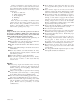


1. Ignition Switch 6. Deck clutch switch 14. Cruise control
2. Choke Lever 7. Operator presence control lever 15. Left deck cover
3. Throttle 8. Anti-scalp wheels 11. Discharge chute 16. Center deck cover
4. Serial number plate 9. Hour meter 12. Pump clutch chain 17. Right deck cover
5. H-bar handle 10. Height adjusting pins 13. Fuel tank 18. Park brake (located under tank)
1
6
2
11
5
13
9
3
12
10
10
10
10
7
7
15
16
17
4
14
8
104893 10/05
3-1
OPERATION
Figure 3-1
Controls
For general location of the controls described in this
section, refer to Figure 3-1.
1. Ignition switch (Fig. 3-2) – a two position switch: off
and run. With key inserted, rotate it clockwise to
RUN position.
2. Throttle (Fig. 3-2) — a cable is linked to engine
throttle for controlling engine speed. Move lever
forward to increase engine rpm, move lever rearward
to decrease engine rpm.
3. Choke control (Fig. 3-2) – a cable is linked to
manually operate the engine choke. When the knob is
in the down position, the choke is in the off (run)
position. When the knob is pulled up, the choke is in
the on (start) position. Do not operate the machine in
the on (start) position.
3. H-bar handle (Fig. 3-1) — this handle controls the
unit’s acceleration, speed, steering direction and
dynamic braking.
4. Deck clutch switch (Fig. 3-2) — this switch engages
the deck. Pull the switch up to engage and push
switch down to disengage the clutch.
IMPORTANT: Never engage clutch with engine
running at high rpm or when the deck is under load.
Clutch, belts or deck could be damaged.
5. Cruise control (Fig. 3-2) — the cruise control, when
engaged, controls the maximum forward speed of the
unit. When it is engaged the H-bar handle can be
rotated forward.
6. Operator presence control levers (Fig. 3-4) —
engages the operator presence switches. If the switch
is not engaged the unit will not operate. Refer to the
Safety Interlock system for more information.
7. Park brake lever (Fig. 3-3) — has three positions:
park brake, drive & bypass valve.
Instrumentation
8. Electronic hour meter (Fig. 3-2) — registers 1/10
hour increments up to 9,999.9 total hours. Connected
to the ignition switch, the meter records the
accumulative time while the engine is running.
Ignition
switch
Choke
Cruise
control
Deck
clutch
switch
Hour
meter
Figure 3-2
Throttle
TrimStar Hydro
Controls
18