Hustler Mini Z Parts Manual ••••••• Hustler Turf Equipment ••••• P.O. Box 7000 ••• Hesston, Kansas • 67062-2097 302612 Rev.
WARNING: The engine exhaust from this product contains chemicals known to the State of California to cause cancer, birth defects or other reproductive harm. IMPORTANT: This engine is not equipped with a spark arrester muffler. It is a violation of California Public Resource Code Section 4442 to use or operate this engine on any forest-covered, brush-covered, or grass-covered unimproved land. Other states or federal areas may have similar laws. This spark ignition system complies with Canadian ICES-002.
Table of Contents Chapter 1 General Information . . . . . . . . . . . . . . . . . . . . . . . . . . . . . . . . . . . . 1-1 Chapter 2 Contents Rivet Nut Installation . . . . . . . . . . . . . . . . . . . . . . . . . . . . . . . . . . . . 2-2 Footrest Assembly . . . . . . . . . . . . . . . . . . . . . . . . . . . . . . . . . . . . . 2-3 Chapter 3 Contents Hydraulic System Installation . . . . . . . . . . . . . . . . . . . . . . . . . . . . . 3-2 Chapter 4 Contents Battery Installation. . . . . . . . . . . .
Chapter 11 Contents Maintenance & Adjustments Safety Precautions. . . . . . . . . . . . . . 11-3 Maintenance. . . . . . . . . . . . . . . . . . . . . . . . . . . . . . . . . . . . . . . . . .11-7 Adjustments. . . . . . . . . . . . . . . . . . . . . . . . . . . . . . . . . . . . . . . . . . 11-15 Index. . . . . . . . . . . . . . . . . . . . . . . . . . . . . . . . . . . . . . . . . . . . . . . . . . . . . . . .
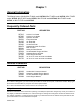
Chapter 1 General Information This Manual covers Hustler Mini Z 19/44 model 927228, Mini Z 19/52 model 927236, Mini Z 23/52 model 927244, Mini Z 24/52 model 927251, Mini Z 20/44 model 927483, Mini Z 20/52 model 927491, & Mini Z 27/52 model 927525. Frequently Ordered Parts PART NO. 027912 027920 768341 786533 791335 789388 785626 068478 785261 785279 785634 772079 747303 784256 783753 DESCRIPTON Lubrizol 7 oz. Bottle Lubrizol 10 oz.
Hardware Description Codes & Abbreviations The following codes are used throughout this parts manual. Refer to this list when ordering parts.
Chapter 2 Contents Rivet Nut Installation . . . . . . . . . . . . . . . . . . . . . . . . . . . . . . . . . . . . . 2-2 Footrest Assembly . . . . . . . . . . . . . . . . . . . . . . . . . . . . . . . . . . . . . . .
Rivet Nut Installation 1 2 INDEX NO. SERVICE PART NO. MFG. PART NO. QTY.
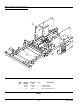
Footrest Assembly 2 1 3 4 5 6 5 7 1 INDEX NO. SERVICE PART NO. MFG. PART NO. QTY. 1 388884 388884 1 MINI Z FLOOR PLATE 2 785485 785485 2 UPPER STEP TREAD 3 785493 785493 1 LOWER STEP TREAD 4 086660 086660 2 NT .375-16 HX LK NY 5 767954 767954 4 FW .406 X .812 X .060 SAE HD ZN 6 781880 781880 2 RUBBER BUMPER 7 052860 052860 2 CS .375-16 X 1.25 HX G5 ZNYC DESCRIPTION NOTES: 1.
2-4 302612 5/05
Chapter 3 Contents Hydraulic System Installation. . . . . . . . . . . . . . . . . . . . . . . . . . . . . . .
Hydraulic System Installation 1 2 4 3 5 7 6 8 12 9 13 10 11 15 16 31 17 32 18 20 22 11 23 12 3 19 8 15 16 21 24 14 17 18 25 20 16 19 26 21 27 28 30 34 29 33 3-2 302612 5/05
Hydraulic System Installation INDEX NO. SERVICE PART NO. MFG. PART NO. QTY. 1 032763 032763 1 BREATHER CAP 2 032771 032771 1 STRAINER 3 368803 368803 1 HYDRAULIC OIL RESERVOIR 4 787614 N/A 1 FITTING, -12MORB/-6FORB 5 787473 N/A 1 FITTING, -6MORB/-6 BEADED TUBE 6 781658 N/A 1 FITTING, STR-8MORB/HEX PLUG 7 787655 N/A 2 CASE DRAIN HOSE ASSEMBLY 8 787465 787465 2 FITTING, 90-6MORB/-6BEADEDTUBE 9 034272 034272 3 NT .312-18 HX G5 ZNYC 10 768523 768523 3 FW .
3-4 302612 5/05
Chapter 4 Contents Battery Installation . . . . . . . . . . . . . . . . . . . . . . . . . . . . . . . . . . . . . . . 4-2 Deck Lift Assembly . . . . . . . . . . . . . . . . . . . . . . . . . . . . . . . . . . . . . . 4-4 Steering and Brake Assembly . . . . . . . . . . . . . . . . . . . . . . . . . . . . . . 4-6 Pump Belt and Pulley Installation . . . . . . . . . . . . . . . . . . . . . . . . . .
Battery Installation 1 2 3 6 5 4 7 8 6 7 9 7 8 10 1 2 12 11 13 14 4-2 302612 5/05
Battery Installation INDEX NO. SERVICE PART NO. MFG. PART NO. QTY. 1 058776 058776 2 NT .312-18 HX NL ZNYC 2 768523 768523 3 FW .343 X .687 X .051/.080 HD ZNYC 3 348417 348417 1 BATTERY CLAMP STRAP 4 785063 785063 1 POSITIVE BATTERY CABLE 5 771428 771428 1 RED BATTERY CABLE BOOT 6 055939 055939 2 CS .250-20 X .750 HX G5 ZNYC 7 029868 029868 4 LW .250 INT-EXT TOOTH ZNYC 8 024927 024927 2 NT .250-20 HX GR.
Deck Lift Assembly 1 3 2 5 4 6 4 6 14 1 12 4 15 11 10 4 7 6 4 6 8 13 14 1 4 14 1 7 6 5 7 6 8 8 1 6 14 9 8 4-4 302612 5/05
Deck Lift Assembly INDEX NO. SERVICE PART NO. MFG. PART NO. QTY. 1 348318 348318 1 STOP HANDLE 2 784488 784488 1 DECK LIFT INDICATOR 3 348284 348284 1 HEIGHT ADJUSTMENT STOP 4 781294 781294 7 CLIP E, 1.00 X.625X .050 5 782995 782995 2 DECK LIFT SPRING 6 704643 704643 8 NT .437-14 HX FLG ZN 7 055749 055749 3 CS .437-14 X 1.750 HX G5 ZNYC 8 348391 348391 4 DECK LIFT CHAIN 9 781831 781831 1 CS .437-14 X 1.750 FULTH G5 ZNYC 10 756270 756270 1 CS .312-18 X 1.
Steering and Brake Assembly 1 2 5 6 4 7 3 8 6 19 9 10 14 13 12 12 17 12 20 18 15 12 13 21 13 24 11 16 6 12 7 28 27 25 26 23 30 6 12 20 22 24 12 29 31 15 6 5 26 40 43 42 2 32 12 13 21 37 41 12 38 44 1 45 34 36 35 47 12 46 21 6 26 33 26 33 39 4-6 302612 5/05
Steering and Brake Assembly 3 4 302612 5/05 INDEX NO. SERVICE PART NO. MFG. PART NO. QTY. 1 781260 781260 2 STEERING BAR GRIP 2 368704 368704 2 STEERING BAR 3 367128 367128 1 CONTROL PANEL 4 368670 368670 2 STEERING ARM MOUNT 5 055822 055822 6 CS .375-16 X .750 HX G5 ZNYC 6 767954 767954 26 FW .406 X .812 X .060 SAE HD ZN 7 781716 781716 4 SS .500-13 X 1.75 SH ZN 8 053199 053199 2 NT .500-13 HX JAM ZNYC 9 036244 036244 4 CS .375-16 X 1.
NOTES: 1. 2. 3. 4. Torque to 280-310 ft.-lbs. Included with wheel motor. Torque brake assembly mounting bolts to 24 ft.-lbs. 783118 used on left wheel. 783126 used on right wheel.
This page intentionally left blank.
Pump Belt and Pulley Installation For mowers with serial numbers prior to 04040580 1 35 1 14 2 27 28 25 30 2 31 32 5 26 33 28 LOCATION FOR RUBBER BUMPER 12 1 29 34 12 8 2 9 2 8 2 3 4 10 9 5 15 6 1 16 14 13 12 4 17 7 20 21 22 18 19 3 23 24 4-10 302612 5/05
Pump Belt and Pulley Installation 5 5 6 INDEX NO. SERVICE PART NO. MFG. PART NO. QTY 1 779876 779876 1 ENGINE SC SINGLE PULLEY 2 212076 212076 1 KEY 1/4 SQ X 1.50 LONG 3 797654 797654 1 FW 1.156 X 1.750 X .250 ZY 4 791251 791251 1 CLUTCH PIGTAIL HARNESS (DIODE) 5 787366 787366 1 WARNER Z CLUTCH 6 783829 783829 1 FW .460X 1.750X .250 ZNYC 7 785048 785048 1 CS .437-20 X 3.00 HX G5 ZNYC 785659 N/A 1 CS .437-20 X 2.50 HX G5 ZNYC 8 083196 083196 4 SS .312-18 X .
7. Electric clutch burnishing procedure: After installing a new clutch, it is important to burnish the clutch to insure maximum deck clutch life. In an open area with no bystanders, set the engine speed to half throttle. Cycle the deck clutch on for 15 seconds, and then off for 15 seconds. Repeat this operation 10 times - it will require about 5 minutes to complete.
Chapter 5 Contents Kawasaki Engine Installation . . . . . . . . . . . . . . . . . . . . . . . . . . . . . . . 5-2 Honda Engine Installation . . . . . . . . . . . . . . . . . . . . . . . . . . . . . . . . . 5-6 Kohler Engine Installation . . . . . . . . . . . . . . . . . . . . . . . . . . . . . . . . 5-10 Fuel System Installation. . . . . . . . . . . . . . . . . . . . . . . . . . . . . . . . . . 5-14 Instrument Panel Installation/Assembly. . . . . . . . . . . . . . . . . . . . . .
Kawasaki Engine Installation 2 PART OF 7 WIRE HARNESS 1 2 6 3 41 7 4 TO BULLET TERMINALS (MALE-BRN) (FEMALE-ORG) 3 5 8 7 11 6 12 9 7 21 3 13 22 10 15 3 1 6 14 18 16 24 TO SPADE 3 TERMINAL PUR 23 7 17 YEL 3 19 22 21 25 27 30 29 43 22 21 20 P/O ENGINE 3 28 42 26 RED/BLK 3 PUR POSITIVE BATTERY CABLE 34 32 35 31 33 7 36 37 40 38 5-2 39 40 7 302612 5/05
Kawasaki Engine Installation 8 INDEX NO. SERVICE PART NO. MFG. PART NO. QTY. 1 786673 786673 1 DONALDSON AIR CLEANER CAP 2 785741 785741 1 MOUNTING BAND 3 057661 057661 2 HOSE CLAMP 4 788943 788943 1 AIR FILTER INDICATOR 5 782763 782763 1 AIR CLEANER 6 034272 034272 10 NT .312-18 HX G5 ZNYC 7 768523 768523 18 FW .343 X .687 X .051/.080HD ZNYC 8 370288 370288 1 MINI Z REMOTE AIR CLEANER BRACKET 9 036236 036236 2 CS .312-18 X 1.
3. Part of Item 24 (783894 Tractor Wire Harness). 4. Engine oil capacity; 2 US quarts. 5. Engine RPM to be set at 3600±50. 6. When installing lower hose clamp on air cleaner hose, install as low as possible (against carburetor inlet). 7. This connector used for optional hydraulic oil cooler fan. 8. Used on mowers with serial numbers 05031839 and higher. This part replaces “O” ring , drain extension, and drain plug, on mowers with serial numbers prior to 05031839, 9.
This page intentionally left blank.
Honda Engine Installation 1 2 9 10 13 14 2 15 12 3 4 17 16 14 5 4 3 7 6 15 PART OF 7 WIRE HARNESS 15 10 8 40 18 11 34 13 37 14 YEL 35 36 35 1 PART OF ENGINE 19 20 22 21 ANTI-ROLLOVER WHEEL BRACKET 23 28 ORG 24 29 39 BRN 1 GRA 1 PUR 1 1 RED/BLK 7 38 25 26 27 14 33 POSITIVE BATTERY CABLE 32 5-6 31 30 14 30 302612 5/05
Honda Engine Installation INDEX NO. SERVICE PART NO. MFG. PART NO. QTY. 1 785014 785014 1 HONDA 24 HP ENGINE (USED ON 927251) 2 784843 784843 1 HONDA MUFFLER 3 720177 720177 2 CS M 8-1.25 X 20 10.9 HXFLZNYC 4 785543 N/A 2 HONDA MUFFLER GASKET 5 784959 784959 1 MUFFLER MANIFOLD 6 785378 785378 1 1.50" MUFFLER CLAMP 7 017004 N/A 5 LW .312 MED SPRING ZNYC 8 782664 N/A 4 NT M8-1.
6. When installing lower hose clamp on air cleaner hose, install as low as possible (against carburetor inlet). 7. This connector used for optional hydraulic oil cooler fan. 8.
This page intentionally left blank.
Kohler Engine Installation 1 12 8 13 11 9 2 14 10 3 4 9 7 2 6 16 14 1 15 14 13 17 9 13 4 14 5 18 21 19 20 22 PART OF 7 WIRE HARNESS 35 23 28 26 24 29 27 25 14 34 33 POSITIVE BATTERY CABLE PUR (P/O ENGINE) 3 RED/BLK 14 30 31 32 2 5-10 302612 5/05
Kohler Engine Installation 4 8 8 INDEX NO. SERVICE PART NO. MFG. PART NO. QTY. 1 788216 788216 1 KOHLER CV740 ENGINE (27 HP) USED ON 927527 794925 794925 1 KOHLER V20S ENGINE (20HP) USED ON 927483 & 927491 2 788018 788018 1 KOHLER MUFFLER 3 029751 029751 2 CS .375-16 X 1.00 HXFLK ZNYC 4 705137 705137 4 FW .391 X 1.250 X .060 ZNYC 5 016899 016899 2 NT .375-16 HXFLK ZNYC 6 785378 785378 1 MUFFLER 1.
replace drain hose, 90° fitting, and drain plug, on mowers with serial numbers prior to 05031280, 9.
This page intentionally left blank.
Fuel System Installation 1 2 SEAT SUPPORT CROSSMEMBER 10 5 6 1 6 2 4 9 6 3 1 7 12 6 11 8 8 1 6 9 4 2 8 9 5-14 1 302612 5/05
Fuel System Installation ITEM NO. SERVICE PART NO. MFG. PART NO. QTY 1 784181 784181 2 FUEL TANK CAP 2 796318 796318 1 RIGHT SIDE FUEL TANK 3 796326 796326 1 LEFT SIDE FUEL TANK 4 791277 N/A 2 FITTING, FUEL TANK 90° 5 745059 745059 1 3-WAY FUEL VALVE 6 000323 000323 6 CLIP 7 000331 000331 3 BLACK CABLE TIE 8 767954 767954 12 FW .406 X .812 X .060 SAE HD ZN 9 055822 055822 12 CS .375-16 X .75 HX G5 ZNYC 10 015818 015818 1 FUEL LINE 12.
Instrument Panel Installation/Assembly 1 2 3 4 1 6 10 5 8 7 1 8 12 5 13 9 1 1 10 11 14 8 6 RIGHT SIDE FUEL TANK 13 12 15a 5a KAWASAKI 10a HONDA 20a FUSE SIZE AND LOCATIONS 5-16 302612 5/05
Instrument Panel Installation/Assembly ITEM NO. SERVICE PART NO. MFG. PART NO. QTY 1 785030 785030 1 Z CHOKE CABLE (KAWASAKI ENGINES) 1 786657 786657 1 Z CHOKE CABLE (HONDA ENGINES) 2 776476 776476 1 PTO SWITCH 3 712257 712257 1 RED INDICATOR LIGHT 4 083022 N/A 2 IGNITION KEY 785808 785808 1 INDAK COATED KEY 5 045898 045898 1 KEY SWITCH 6 059832 059832 6 NT #10-24 HX NL ZN 7 026237 N/A 3 RELAY 8 704932 704932 6 FW .219 X .500 X .
Electrical Schematic–Kawasaki Engines (783894) 5-18 302612 5/05
Electrical Schematic–Kawasaki Engines (783894) 302612 5/05 5-19
Electrical Schematic–Honda Engines (787200) 5-20 302612 5/05
Electrical Schematic–Honda Engines (787200) 302612 5/05 5-21
Electrical Schematic–Kohler Engines (788000) 5-22 302612 5/05
Electrical Schematic–Kohler Engines (788000) 302612 5/05 5-23
5-24 302612 5/05
Chapter 6 Contents Front Wheel Assembly. . . . . . . . . . . . . . . . . . . . . . . . . . . . . . . . . . . . 6-2 Front Wheel Breakdown - 786061 . . . . . . . . . . . . . . . . . . . . . . . . . . . 6-4 Drive Wheel Assembly. . . . . . . . . . . . . . . . . . . . . . . . . . . . . . . . . . . . 6-5 Anti-Rollover Wheel Assembly . . . . . . . . . . . . . . . . . . . . . . . . . . . . .
Front Wheel Assembly 1 2 3 4 2 TRACTOR FRAME 5 1 2 3 4 6 2 5 2 5 7 8 9 6 10 10 2 5 11 7 8 10 9 10 12 1 12 6-2 1 302612 5/05
Front Wheel Assembly INDEX NO. SERVICE PART NO. MFG. PART NO. QTY 1 705954 705954 2 CS .500-13 X 1.25 HX G5 ZN 2 344267 344267 2 FW .510 X 2.15 X .187 SPL ZN 3 712976 712976 2 FW .531 X 1.375 X .125 ZNYC 4 263517 263517 2 BEARING DISC 5 784223 784223 4 BEARING W/O COLLAR 6 784603 784603 2 SPACER 7 045765 045765 2 FW 1.030 X 1.500 X.134 ZN 8 366625 366625 2 FORK 9 786731 786731 2 CS .750-10 X 8.00 HX GR5 ZYNC 10 025296 025296 4 FW .760 X 1.625 X .
Front Wheel Breakdown - 786061 2 1 3 1 5 4 ITEM NO. SERVICE PART NO. MFG. PART NO. QTY 1 786103 N/A 2 WHEEL BEARING 2 747402 N/A 1 TIRE 13 X 5.00 3 786079 N/A 1 WHEEL 4 019521 N/A 1 TIRE VALVE 5 015511 N/A 1 GREASE FITTING 45 DEG 1/4 2 2 DESCRIPTION NOTES: 1. Inflate tire to 8-10 psi. 2. Service parts for 795245 (Optional Semi-Pneumatic Tire/Wheel Assembly), also.
Drive Wheel Assembly 1 6 2 4 3 5 1 INDEX NO. SERVICE PART NO. MFG. PART NO. QTY 1 782078 782078 2 2 782284 N/A TIRE 23 X 9.50-12 3 782086 N/A WHEEL 10 X 7.5 4 019521 N/A TIRE VALVE 5 061077 061077 5 WHEEL NUT (QTY PER WHEEL) 6 770859 N/A 5 1/2" WHEEL LUG STUD (QTY PER WHEEL) DESCRIPTION WHEEL/TIRE ASSEMBLY 23 X 9.50 NOTES: 1. Torque to 65-75 ft. lbs. 2. Inflate tire to 8-10 psi.
Anti-Rollover Wheel Assembly 4 3 5 1 6 5 1 5 2 1 7 5 2 4 7 8 INDEX NO. SERVICE PART NO. MFG. PART NO. QTY 1 034272 034272 6 NT .312-18 HX G5 ZNYC 2 768523 768523 6 FW .343 X .687 X .051/.080 HD ZNYC 3 350835 350835 2 ANTI ROLLOVER WHEEL BRACKET 4 068239 068239 2 CS .500-13 X 4.500 HX G5 ZN 5 767962 767962 4 FW .531 X 1.063 X .090 SAE HD ZN 6 781567 781567 2 NT .50-13 HX LK NY 7 016253 016253 6 CB .312-18 X .
Chapter 7 Contents Deck Assembly . . . . . . . . . . . . . . . . . . . . . . . . . . . . . . . . . . . . . . . . . 7-2 Deck Pulley Assembly . . . . . . . . . . . . . . . . . . . . . . . . . . . . . . . . . . . . 7-4 Blade Spindle Assembly Breakdown . . . . . . . . . . . . . . . . . . . . . . . . .
Deck Assembly 2 4 3 1 9 3 5 10 7 8 4 11 4 10 6 2 1 17 16 8 12 13 15 14 8 12 13 2 16 13 8 15 4 16 15 18 15 2 13 2 16 13 12 4 15 14 5 2 16A 14 13 12 1A 2 12A 13A 14A 44" DECK 15A 7-2 302612 5/05
Deck Assembly 5 4 INDEX NO. SERVICE PART NO. MFG. PART NO. QTY. 1 546408 367730 1 52" MINI-Z DECK 1A 546382 367946 1 44" MINI-Z DECK DESCRIPTION 2 357111 357111 1 DISCHARGE CHUTE 3 063297 063297 2 SB .375 X .50 SH .312-18 TD ZN 4 767954 767954 20 FW .406 X .812 X .060 SAE HD ZN 5 054502 054502 8 NT .375-16 HX GRD 5 ZNYC 6 357103 357103 1 DISCHARGE CHUTE MOUNT BRACKET 7 058776 058776 2 NT .
Deck Pulley Assembly 1 2 4 3 2 10 5 11 6 7 8 12 7 21 9 13 14 7 13 14 15 1 22 20 16 17 22 18 22 19 18 26 23 25 22 21 24 27 29 18 17 7-4 1 302612 5/05
Deck Pulley Assembly INDEX NO. SERVICE PART NO. MFG. PART NO. QTY. 1 789388 789388 1 52" DECK BELT 791335 791335 1 44" DECK BELT 2 784199 784199 1 CS .312-18 X 1.25 FLT SH ZNYC 3 017129 017129 6 FW .440 X 1.00 X .083 ZNYC 4 785832 785832 2 DECK IDLER UHMW CLAMP 5 787069 787069 2 DECK IDLER UHMW RISER 6 025007 025007 1 CS .625-11 X1.75 HX G5 ZNYC 7 028118 028118 4 FW .62 X 1.00 X.134 ZNYC 8 781856 781856 1 IDLER NHI 5.
4. Used on mower with serial number prior to 05050800. 30 33 2 31 4 3 11 5 6 7 12 8 7 13 32 5. Used on mowers with serial number 05050800 and higher. 6.
Blade Spindle Assembly Breakdown 1 2 3 4 2 5 INDEX NO. SERVICE PART NO. MFG. PART NO. QTY.
7-8 302612 5/05
Chapter 8 Contents Deck Installation . . . . . . . . . . . . . . . . . . . . . . . . . . . . . . . . . . . . . . . . 8-2 Deck Belt Routing and Tensioning. . . . . . . . . . . . . . . . . . . . . . . . . . .
Deck Installation TRACTOR ASSEMBLY 1 1 2 3 5 4 DECK ASSEMBLY 5 INDEX NO. SERVICE PART NO. MFG. PART NO. QTY. 1 055749 055749 4 CS .437-14 X 1.750 HX G5 ZNYC DESCRIPTION 2 051169 051169 2 CS .750-10X3.000 HX G5 ZNYC 3 025296 025296 4 FW .760 X 1.625 X.08 ZNYC 4 061101 061101 2 NT .750-10 HX NL ZN 5 704643 704643 8 NT .437-14 HX FLG ZN NOTES: 1. 52" Deck installation shown, 44" Deck installation is similar.
Deck Belt Routing and Tensioning 1 NOTES: 1. Spring length after tensioning new belt, measured from outside of hook to outside of hook. 2. Route belt as shown.
8-4 302612 5/05
Chapter 9 Contents Tractor Decals . . . . . . . . . . . . . . . . . . . . . . . . . . . . . . . . . . . . . . . . . . 9-2 52" Deck Decals . . . . . . . . . . . . . . . . . . . . . . . . . . . . . . . . . . . . . . . . 9-4 44" Deck Decals . . . . . . . . . . . . . . . . . . . . . . . . . . . . . . . . . . . . . . . .
Tractor Decals B B 2 3 A 1 A5 4 6 7 8 11 9 12 10 13 14 BOTTOM OF SEAT PAN 15 16 9-2 302612 5/05
Tractor Decals INDEX NO. SERVICE PART NO. MFG. PART NO. QTY. 1 784702 784702 1 INSTRUMENT PANEL DECAL 2 782128 782128 1 Z SERVICE DECAL 3 779280 779280 1 HOT & HYD OIL DECAL 4 727008 727008 1 HYD PRESSURE DECAL 5 791848 791848 1 FUEL INDICATOR DECAL 6 782573 782573 1 FIRST ZERO TURN DECAL 7 786814 786814 1 HUSTLER MINI-Z ID DECAL 8 727172 727172 1 "MADE IN U.S.A.
52" Deck Decals 1 2 8 3 7 4 3 5 5 6 INDEX NO. SERVICE PART NO. MFG. PART NO. QTY. 1 781419 781419 1 BELT ROUTING DECAL 2 760637 760637 1 MOWER DECK QUICK REF DECAL 3 727438 727438 2 WHIRLING BLADES DECAL 4 727420 727420 1 DEFLECTOR SHIELD DECAL 5 727453 727453 2 BELT & PULLEY DECAL 6 785535 785535 1 DECK I.D. 52" DECAL 7 727172 727172 1 "MADE IN U.S.A.
44" Deck Decals 1 2 3 8 4 7 3 5 5 6 INDEX NO. SERVICE PART NO. MFG. PART NO. QTY. 1 781419 781419 1 BELT ROUTING DECAL 2 760637 760637 1 MOWER DECK QUICK REF DECAL 3 727438 727438 2 WHIRLING BLADES DECAL 4 727420 727420 1 DEFLECTOR SHIELD DECAL 5 727453 727453 2 BELT & PULLEY DECAL 6 784801 784801 1 DECK 44" ID DECAL 7 727172 727172 1 "MADE IN U.S.A.
9-6 302612 5/05
Chapter 10 Contents Seat Installation . . . . . . . . . . . . . . . . . . . . . . . . . . . . . . . . . . . . . . . .
Seat Installation 5 19 6 18 3 3 7 4 9 1 2 11 1 10 8 12 15 13 16 14 16 9 2 17 10-2 302612 5/05
Seat Installation INDEX NO. SERVICE PART NO. MFG. PART NO. QTY. 1 036244 036244 1 CS .375-16 X 1.00 HX G5 ZNYC 2 767954 767954 5 FW .406 X .812 X .060 SAE HD ZN 3 748756 748756 1 SPRING PLUNGER LATCH 4 389940 389940 1 SEAT LATCH BRACKET 5 781617 781617 3 RUBBER BUMPER 6 722199 722199 1 2" WIDE SCOTCH POLYURETHANE 6" 7 793661 793661 1 MICHIGAN STANDARD SEAT 781104 781104 1 MILSCO STANDARD SEAT 8 000331 000331 3 SMALL/SHORT WIRE TIE 9 086660 086660 3 NT .
Chapter 11 Contents Maintenance & Adjustments Safety Precautions . . . . . . . . . . . . . . .11-3 Maintenance . . . . . . . . . . . . . . . . . . . . . . . . . . . . . . . . . . . . . . . . . . .11-7 Adjustments . . . . . . . . . . . . . . . . . . . . . . . . . . . . . . . . . . . . . . . . . .
11-2 302612_0606
SAFETY PRECAUTIONS ▲ ▲ This safety alert symbol is used to call attention to a message intended to provide a reasonable degree of PERSONAL SAFETY for operators and other persons during the normal operation and servicing of this equipment. DANGER – denotes immediate hazards which WILL result in severe personal injury or death. ▲ ▲ WARNING - denotes a hazard or unsafe practice which COULD result in severe personal injury or death. ▲ This manual uses two other words to highlight information.
Using a ramp ▲ Grass collection system components are subject to wear, damage and deterioration, which could expose moving parts or allow objects to be thrown. Frequently check components and replace with manufacturer’s recommended parts, when necessary. ▲ Use only genuine Hustler replacement parts to ensure that original standards are maintained ▲ Use extreme caution when loading and unloading a unit with a ramp. ▲ Use only a single, full width ramp; do not use individual ramps for each side of the unit.
Safety and Instruction Decals ▲ Specific safety warning decals are located on the equipment near the immediate areas of potential hazards. These decals should not be removed or obliterated. Replace them if they become non-readable. The following illustrations show the various safety decals that are located on the machine. A brief explanation is shown to help the operator understand the meanings of these decals. Do not smoke while refueling. Do not fill tank with engine running, or while the engine is hot.
11-6 302612_0606
MAINTENANCE MAINTENANCE LOCATOR CHART 3 6 7 13 5 12 12 10 2B 16 2C 11 4 1A 1B 6 2A 13 12 12 1A. Engine Oil Fill & Dipstick (Kawasaki & Honda) 1B. Engine Oil Fill & Dipstick (Kohler) 2A. Fuel Filter (Kawasaki) 2B. Fuel Filter (Honda) 2C. Fuel Filter (Kohler) 3. Engine Air Cleaner 4. Engine Oil Drain Plug 5. Battery 6. Fuel Tanks 7. Hydraulic Oil Reservoir 8. Deck Pusher Arm Zerks (2) 9. Hydraulic Oil Filter 10. Gauge Wheel Bearing Zerks (2) 11. Engine Oil Filter 12. Deck Height Pivot Zerks (4) 13.
SERVICE AT INTERVALS INDICATED Verify safety start interlock system Visually inspect unit for loose hardware and/or damaged parts Visually inspect tires Check oil level, engine (1) Clean air intake screen (5) Check fuel level Blades - sharpen & securely fastened Discharge chute - securely in place & in lowest position Clean engine and pump compartments Replace air cleaner paper element (5) Grease deck pusher arms Grease pump idler Grease deck height pivots Grease gauge wheel bearings Change engine oil & fil
multi-purpose grease. 3. Grease the pump idler per the Maintenance Schedule. Use SAE multi-purpose grease. 4. Grease the two deck pusher arm pivots per the Maintenance Schedule. Use SAE multi-purpose grease. Battery Electrical system The electrical system is a 12 volt, negative ground. Recommended battery size is a garden tractor BCI group U1R with 225 or better cranking AMP rating. A maintenance-free battery is recommended.
Seat platform catch Fuel tank Seat platform Figure 11-7 Control lever 1. Fill the filter element with clean system oil. Smear a light coating of oil on upper surface of rubber seal. 2. Install the filter element on base. Tighten the oil filter by hand until the filter seal makes contact with the filter head, then tighten an additional 3/4 turn with a an oil filter wrench. — DO NOT OVERTIGHTEN. 3.
Valve grommet Fuel filter Fuel shut-off valve Figure 11-9A Kawasaki engine Fuel valve (shown in closed position) Figure 11-8A Right fuel tank Fuel filter Left fuel tank Figure 11-9B dipstick and oil filler tube are located at the rear of the machine (Fig. 1110A & 11-10B). Tractor must be setting level when checking oil. Refer to engine manual and maintenance schedule for oil recommendation and capacities.
Engine oil filler tube Kawasaki Engine Kohler engine Engine oil drain plug Engine oil drain plug Engine oil filter Engine oil filter Figure 11-10A Engine oil filler tube Figure 11-10C Honda Engine Incorrect air cleaner element Engine oil drain plug Engine oil filter Figure 11-10B It is important to note that whenever an air filter element is cleaned by any method, the person or company performing the cleaning assumes responsibility for the integrity of the filter from then on.
Pre-cleaner Viewed from bottom for unit 1. Pump belt 2. Engine pulley 3. Pump idler pulley 4. Pump idler arm 5. Pump pulley 6. Electric deck clutch 7. Pump idler spring 1 5 Canister 5 4 Figure11-11 2, 6 7 3 Figure 11-13 Reset button 2 5 Indicator 2 Figure 11-12 2 maintenance are specified in the Engine Owner’s manual. Please refer to this manual for engine servicing, lubricating oil levels with quality and viscosity recommendations, bolt torques, etc.
Mower blade removal Use a 15/16" wrench to remove the 5/8" cap screw holding the blade to the spindle shaft from underneath. Sharpen the blades on a grinder following pattern as shown (Fig. 1115). Touch-up sharpening can be done with a file. Check the blades for balance following grinding. A commercial balancing tool is available through most hardware supply stores, or balancing can be done by placing the blade on an inverted line punch or 5/8" bolt. Blade should not lean or tilt.
ADJUSTMENTS Introduction Your Mini Z was adjusted before it left the factory and was checked during predelivery setup. However, after start-up and continued use, a certain amount of break-in wear will cause some adjustments to change. Remain alert for unusual noises, they could be signaling a problem. Visually inspect the machine for any abnormal wear or damage. A good time to detect potential problems is while performing scheduled maintenance service.
Upper control lever Spring housing Front ball stud Cap screw Steering dampener with spring Lower control lever Figure 11-21 Control lever stops The control lever stops (Fig. 11-20) are designed to do two things: First, and most important, they must keep the pumps from bottoming out internally. Secondly, the stops may be adjusted to help drive straight when the control levers are pushed forward against the stops. To keep the pumps from bottoming out internally use the following procedure: 1.
NOTE: The front brake link is not adjustable. Fig. 11-23 2. Raise and block the tractor up so the drive wheels are off of the floor. 3. Open the hydraulic pump’s bypass valve (Fig. 11-24), on the side that is being adjusted, by turning bypass valve counter clockwise one-half to one revolution. The valve stems on each hydraulic pump are located near the top and are identified as a hex stud. 4. Rotate the tire. The tire should rotate.
Spring Tension idler Pump drive belt Blocks Figure 11-32 Figure 11-29 Stop handle Spring Height adjusting stop Tension idler Chain Figure 11-30 Figure 11-33 Deck lift threaded rod Spring Extension 7.75” Normal Spring Length 6.0” 1.75” Nut Nut Figure 11-31 excessively worn or damaged. As belt stretches and wears in, adjustment may become necessary. To increase belt tension, move the spring chain one (or more) link(s) at the anchor bracket (Fig. 11-30). Installed spring length should be 7.
18. Tighten the hardware holding the chain and adjuster onto the deck lift arm. 19. Go to the right rear of the tractor. 20. Make sure that there is still slack in the chain. If not, loosen the two nuts on the block holding the threaded rod until there is slack in the deck lift chain. Fig. 11-35 21. Tighten the appropriate nut until the chain just becomes tight, making sure that the deck stays tight against the 3" block. 22.
11-20 302612_0606
INDEX PAGE Access to engine and hydraulic pump............................11-9 Adjustment introduction...............................................11-15 Belt replacement...........................................................11-13 Burnishing the electric clutch.........................................11-9 Control lever adjustment ..............................................11-16 Control lever stops .......................................................11-16 Decals....................................
11-22 302612_0606
10-4 302612 5/05
Numerical Index Part No. Page No. Part No. Page No. Part No. Page No.
Part No. 747402 748681 748756 756270 762195 763318 763946 765339 767954 767962 768127 768333 768341 768515 768523 768820 769166 770859 771428 771436 772079 776476 777656 778217 778365 778423 778738 779132 779280 779447 779611 779850 779876 780718 780841 781047 781062 781104 781153 781211 781229 781260 781286 781294 781302 781385 781419 781526 Page No.
Part No. Page No. Part No. Page No. Part No. Page No.