36" & 42" Deck Parts Manual •••• P.O. Box 7000 ••• Hesston, Kansas • 67062-2097 333559 Rev.
WARNING: The engine exhaust from this product contains chemicals known to the State of California to cause cancer, birth defects or other reproductive harm. IMPORTANT: This engine is not equipped with a spark arrester muffler. It is a violation of California Public Resource Code Section 4442 to use or operate this engine on any forest-covered, brush-covered, or grass-covered unimproved land. Other states or federal areas may have similar laws. This spark ignition system complies with Canadian ICES-002.
Table of Contents Chapter 1 General Information . . . . . . . . . . . . . . . . . . . . . . . . . . . . . . . . . . . . 1-1 Chapter 2 Contents Tractor Frame Rivet Nut Installation . . . . . . . . . . . . . . . . . . . . . . . . 2-2 Engine Guard and Anti-rollover Bracket Assemblies . . . . . . . . . . . 2-3 Footrest Assembly . . . . . . . . . . . . . . . . . . . . . . . . . . . . . . . . . . . . . 2-4 Chapter 3 Contents Battery Installation. . . . . . . . . . . . . . . . . . . . . . . . . . . . . . . . . . .
c-2 333559 8/06
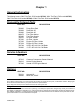
Chapter 1 General Information This Manual covers “Mini” FasTrak 15/36 model 927343, “Mini” FasTrak 17/42 model 927350, “Mini” FasTrak 16/42 model 927368, & “Mini” FasTrak 16/36 model 927376, Frequently Ordered Parts PART NO. 793836 793828 793893 068478 785626 794370 787226 747303 787234 793794 793802 DESCRIPTION Pump Drive Belt Deck Belt 36" Deck Belt 42" Fuel Filter Kohler Fuel Filter Honda Air Filter, Kohler Air Filter, Honda Engine Oil Filter, Kohler Engine Oil Filter, Honda 20.50" 42D X 0.
Hardware Description Codes & Abbreviations The following codes are used throughout this parts manual. Refer to this list when ordering parts.
Chapter 2 Contents Tractor Frame Rivet Nut Installation . . . . . . . . . . . . . . . . . . . . . . . . . 2-2 Engine Guard and Anti-rollover Bracket Rivet Nuts. . . . . . . . . . . . . . 2-3 Footrest Assembly . . . . . . . . . . . . . . . . . . . . . . . . . . . . . . . . . . . . . . .
Tractor Frame Rivet Nut Installation 2 1 INDEX NO. 1 2 SERVICE PART NO. MFG. PART NO. QTY.
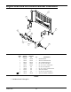
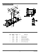
Engine Guard and Anti-rollover Bracket Assemblies 1 3 3 2 4 3 8 5 9 6 7 1 INDEX NO. SERVICE PART NO. MFG. PART NO. QTY. 1 316836 316836 1 ENGINE GUARD 2 320580 320580 2 ANTI ROLLOVER BRACKET 3 808493 808493 8 3/8-16 THREAD RIVET NUT 4 781567 781567 2 NT .50-13 HX LK NY ZNYC 5 344267 344267 4 FW .510 X 2.15 X .187SPL ZNYC 6 053199 N/A 2 NT .500-13 HX JAM ZNYC 7 767962 N/A 4 FW .531 X 1.063 X .
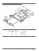
Footrest Assembly 3 1 4 2 1 6 7 6 5 7 INDEX NO. SERVICE PART NO. MFG. PART NO. QTY. DESCRIPTION 1 011320 011320 4 CB .375-16 X .75 STD ZN 2 785485 785485 2 UPPER STEP TREAD 3 793844 793844 2 LOWER STEP TREAD 4 320267 320267 1 FLOOR PLATE 36" MOWERS 316844 316844 1 FLOOR PLATE 42" MOWERS 5 767954 767954 2 FW .406 X .812 X .060 SAE HD ZN 6 076422 076422 2 FW.406X 1.000X.06 7 054502 054502 4 NT .
Chapter 3 Contents Battery Installation . . . . . . . . . . . . . . . . . . . . . . . . . . . . . . . . . . . . . . . 3-2 Deck Lift Assembly . . . . . . . . . . . . . . . . . . . . . . . . . . . . . . . . . . . . . . 3-3 Hydro Transmission Installation. . . . . . . . . . . . . . . . . . . . . . . . . . . . . 3-4 Steering and Brake Assembly . . . . . . . . . . . . . . . . . . . . . . . . . . . . . .
Battery Installation 1 2 3 5 4 6 3 2 7 8 4 4 PART OF WIRE HARNESS (BLK) 2 9 INDEX NO. SERVICE PART NO. MFG. PART NO. QTY. 1 314989 314989 1 2 024927 024927 3 NT .250-20 HX GR.5 ZNYC 3 055939 055939 2 CS .250-20 X .75 HX G5 ZNYC 4 029868 029868 4 LW .
Deck Lift Assembly 1 2 3 6 7 8 9 5 7 4 9 8 12 13 14 7 9 8 1 5 1 11 10 9 9 11 15 7 17 16 16 7 INDEX NO. SERVICE PART NO. MFG. PART NO. QTY. 1 348318 348318 1 2 348284 348284 1 HEIGHT ADJUSTMENT STOP 3 793505 793505 1 DECK HEIGHT INDICATOR 4 782995 782995 1 DECK LIFT SPRING 5 055749 055749 2 CS .437-14 X 1.75 HX G5 ZNYC 6 334045 334045 1 DECK LIFT LINK 7 704643 704643 6 NT .437-14 HX FLG ZN 8 025296 025296 4 FW .760 X 1.625 X .08 ZNYC E CLIP 1.
Hydro Transmission Installation 1 12 1 3 2 4 5 10 6 9 8 12 7 21 12 4 13 1 12 1 2 13 11 14 19 15 20 17 3-4 16 18 333559 8/06
Hydro Transmission Installation INDEX NO. SERVICE PART NO. MFG. PART NO. QTY. 1 710087 710087 8 CS .312-18 X 2.50 HX G5 ZNYC 2 028118 028118 3 FW .62 X 1.00 X .134 ZNYC 3 794404 794404 1 PULLEY 4 025007 025007 2 CS .625-11 X 1.75 HX G5 ZNYC 5 793836 793836 1 A-SECTION PUMP BELT 6 792911 792911 1 EZT LEFT PUMP/MOTOR COMBO 7 792895 792895 1 EZT RIGHT PUMP/MOTOR COMBO 8 718288 718288 1 FW .516 X .875 X .09 ZNYC 9 035238 035238 1 LW .
Steering and Brake Assembly 1 2 3 4 8 7 8 11 4 5 9 12 14 13 13 15 11 6 20 4 4 10 19 10 8 8 16 4 17 22 11 5 23 21 8 11 18 7 24 8 9 13 13 25 27 28 35 29 29 36 8 21 8 10 40 37 38 39 21 26 11 28 41 34 29 30 28 41 32 33 SEE NOTE 3 3-6 8 31 11 333559 8/06
Steering and Brake Assembly INDEX NO. 4 MFG. PART NO. QTY. DESCRIPTION 1 781260 N/A 2 STEERING BAR GRIP 2 360487 360487 2 STEERING BAR 3 600221 600221 2 CENTERING DAMPER 783696 783696 2 CENTERING DAMPER 4 767954 767954 10 FW .406 X .812 X .060 SAE HD ZN 5 086660 086660 6 NT .375-16 HX LK NY 6 705178 705178 4 CS .375-16 X 1.75 HX G5 ZNYC 7 034272 034272 4 NT .312-18 HX G5 ZNYC 8 768523 768523 20 FW .343 X .687 X .051/.
(352112/352054 Brake Pivots). 2. Apply grease to items 12 (768259 Igus® Bushings) (see owners manual). 3. Order these parts for mowers with serial number prior to 05040000. 4. Includes Item 1 (781260 Steering Bar Grip). 5. Use on mowers with serial numbers prior to 060171975.
Chapter 4 Contents Honda 16 HP Engine Installation. . . . . . . . . . . . . . . . . . . . . . . . . . . . 4-2 Kohler 15 & 17 HP Engine Installation. . . . . . . . . . . . . . . . . . . . . . . . 4-4 Fuel System Installation. . . . . . . . . . . . . . . . . . . . . . . . . . . . . . . . . . . 4-6 Instrument Panel Installation . . . . . . . . . . . . . . . . . . . . . . . . . . . . . . . 4-8 Honda 16HP Electrical Schematic (793083) . . . . . . . . . . . . . . . . . .
Honda 16 HP Engine Installation NEGATIVE BATTERY CABLE FROM RECTIFIER 2 1 3 1 RED/BLK 37 6 POSITIVE BATTERY CABLE 4 5 23 2 TO ENGINE (4 WIRES) 1 YEL PART OF ENGINE 11 7 12 8 13 8 10 16 9 14 15 17 18 19 21 20 22 2 24 28 26 25 4 PART OF ENGINE 27 33 31 32 30 29 2 35 36 34 4-2 333559 8/06
Honda 16 HP Engine Installation INDEX NO. SERVICE PART NO. MFG. PART NO. QTY. DESCRIPTION 1 785394 785394 1 HONDA 16HP ENGINE (USED ON 927368 & 927376) 2 739144 792796 3 CS M 6-1.0 X 12 10.9 HXFL ZN 3 378273 378273 1 16HP EXHAUST HEAT SHIELD 4 034272 034272 6 NT .312-18 HX G5 ZNYC 5 712927 712927 4 FW .344 X 1.00 X .12 HRD ZNYC 6 782664 782664 1 NT M8-1.25 HX STAINLESS STEEL 7 024927 024927 2 NT .250-20 HX GR.5 ZNYC 8 768515 768515 4 FW .281 X .625 X .051/.
Kohler 15 & 17 HP Engine Installation TTO 33 TO STARTER SELENOID 1 1 FROM NEGATIVE BATTERY TEMINAL 3 1 1 6 7 4 2 RED 2 PUR TO BATTERY 5 5 4 9 14 5 RED/BLK 2 8 12 4 5 15 7 13 7 15 16 10 11 18 17 6 19 6 20 21 22 3 2 YEL 29 23 28 30 26 27 31 32 31 25 4-4 24 333559 8/06
Kohler 15 & 17 HP Engine Installation INDEX NO. SERVICE PART NO. MFG. PART NO. QTY. 1 792945 792945 1 KOHLER 15 HP ENGINE SV470S 792952 792952 1 KOHLER 17 HP ENGINE SV530S DESCRIPTION 2 793133 793133 1 KOHLER 15 & 17 HP EXHAUST MANIFOLD 3 739144 792796 1 CS M 6-1.0 X 12 10.9 HX 4 024927 024927 4 NT .250-20 HX GR 5 ZNYC 5 768515 768515 6 FW .281 X .625 X .051/.080 HD ZNYC 6 706531 706531 1 GM 1.12 X 1.75 X 1.37 X .12 7 794644 794644 1 GM 1.50 X 2.12 X 1.75 X .
Fuel System Installation 1 2 4 5 11 14 8 1 14 1 3 9 4 13 8 9 10 1 4 5 12 4 4 9 8 10 6 6 7 4-6 333559 8/06
Fuel System Installation INDEX NO. SERVICE PART NO. MFG. PART NO. QTY. 1 779306 779306 2 3.5" FUEL CAP 2 792978 792978 1 36/42 LEFT SIDE FUEL TANK 3 792960 792960 1 36/42 RIGHT SIDE FUEL TANK 4 000323 000323 6 CLIP 5 745059 745059 1 3-WAY FUEL VALVE 6 767954 767954 10 FW .406 X .812 X .060 SAE HD ZN 7 055822 055822 8 CS .375-16 X .75 HX G5 ZNYC 8 054502 054502 2 NT .
Instrument Panel Installation 1 2 3 4 6 5 8 7 9 1 10 5 1 11 1 7 8 12 13 13 12 10a 20a FUSE SIZE AND LOCATION 4-8 333559 8/06
Instrument Panel Installation INDEX NO. SERVICE PART NO. MFG. PART NO. QTY. 1 786657 786657 1 CHOKE CABLE (KOHLER) 785030 785030 1 CHOKE CABLE (HONDA) DESCRIPTION 2 776476 776476 1 PTO SWITCH 3 712257 712257 1 RED INDICATOR LIGHT 4 083022 N/A 2 IGNITION KEY 785808 785808 1 INDAK COATED KEY 5 045898 045898 1 KEY SWITCH 6 714998 714998 2 MS #10-24 X .625 HX ZN 7 704932 704932 4 FW .219 X .500 X .
Honda 16HP Electrical Schematic (793083) 4-10 333559 8/06
Honda 16HP Electrical Schematic (793083) 333559 8/06 4-11
Kohler 15 & 17 HP Electrical Schematic (793117) 4-12 333559 8/06
Kohler 15 & 17 HP Electrical Schematic (793117) 333559 8/06 4-13
4-14 333559 8/06
Chapter 5 Contents Front Wheel Assembly. . . . . . . . . . . . . . . . . . . . . . . . . . . . . . . . . . . . 5-2 Front Wheel Breakdown - 768044 . . . . . . . . . . . . . . . . . . . . . . . . . . . 5-3 Drive Wheel Assembly. . . . . . . . . . . . . . . . . . . . . . . . . . . . . . . . . . . .
Front Wheel Assembly 1 2 3 3 2 4 9 1 2 3 5 3 4 8 4 3 6 5 8 3 4 7 6 10 8 9 1 2 10 11 INDEX NO. SERVICE PART NO. MFG. PART NO. QTY. 1 705954 705954 2 DESCRIPTION CS .500-13 X 1.25 HX G5 ZNYC 2 344267 344267 2 FW .510 X 2.15 X .187 SPL ZNYC 3 712976 712976 2 FW .531 X 1.375 X .125 ZNYC 4 784223 784223 4 BEARING 5 784603 784603 2 SPACER 6 339689 339689 2 CASTER FORK 7 781567 781567 2 NT .50-13 HX LK NY ZNYC 8 767962 767962 4 FW .531 X 1.063 X .
Front Wheel Breakdown -768044 2 768044 1 2 INDEX NO. SERVICE PART NO. MFG. PART NO. QTY 1 772814 N/A 1 3/4" ROLLER BEARING 2 772806 N/A 2 BEARING CAP NOTES: 1. Inflate tire to 8-10 psi.
Drive Wheel Assembly 1 6 4 2 3 2 INDEX NO. 3 5 SERVICE PART NO. MFG. PART NO. 1 783134 783134 2 WHEEL/TIRE ASSEMBLY 18 X 8.50 (PER 36" MOWER) 2 783142 N/A 1 TIRE 18 X 8.5-8 QTY DESCRIPTION 3 783159 N/A 1 WHEEL ASSY 8.00 X 7.00 4 019521 N/A 1 TIRE VALVE 5 061077 061077 8 WHEEL NUT (PER MOWER) 6 793406 793406 8 SPACER, .375TH X .53 ID X 1.0 0D ZN (PER MOWER) 1 784264 784264 2 WHEEL/TIRE ASSY 18 X 9.50 (PER 42” MOWER) 2 784272 N/A 1 TIRE 18 X 9.
Chapter 6 Contents Deck Assembly 36" . . . . . . . . . . . . . . . . . . . . . . . . . . . . . . . . . . . . . . 6-2 Deck Pulley Assembly 36". . . . . . . . . . . . . . . . . . . . . . . . . . . . . . . . . 6-4 Deck Assembly 42" . . . . . . . . . . . . . . . . . . . . . . . . . . . . . . . . . . . . . . 6-8 Deck Pulley Assembly 42". . . . . . . . . . . . . . . . . . . . . . . . . . . . . . . . 6-10 Blade Spindle Assembly Breakdown . . . . . . . . . . . . . . . . . . . . . . . .
Deck Assembly 36" 1 4 2 5 2 6 7 3 8 9 13 10 12 8 9 9 10 11 12 13 9 12 15 16 14 17 18 6-2 17 19 333559 8/06
Deck Assembly 36" INDEX NO. 1 SERVICE PART NO. MFG. PART NO. QTY. DESCRIPTION 1 330399 330399 1 DISCHARGE CHUTE 2 086660 086660 2 NT .375-16 HX LK NY 3 036244 036244 2 CS .375-16 X 1.00 HX G5 ZNYC 4 781880 781880 1 BUMPER, .500X 1.00X .312 X.188 5 054502 054502 2 NT .375-16 HX GRD 5 ZNYC 6 767954 767954 2 FW .406 X .812 X .060 SAE HD ZN 7 352500 352500 1 DISCHARGE CHUTE BASE 8 322974 322974 2 PULLBAR PIN 9 768523 768523 4 FW .343 X .687 X .051/.
Deck Pulley Assembly 36" 1 2 3 4 5 6 7 8 11 10 9 13 12 2 1 15 18 3 14 16 19 4 1 15 16 20 17 4 19 20 21 21 22 22 24 20 22 24 25 20 23 26 25 27 16 16 1 15 6-4 333559 8/06
Deck Pulley Assembly 36" 3 3 3 3 3 INDEX NO. SERVICE PART NO. MFG. PART NO. 1 793828 793828 1 A-SECTION BELT (FASTRAK 36") 2 025007 025007 2 CS .625-11 X 1.75 HX G5 ZNYC 3 046821 046821 2 FW .656 X 2.00 X .078 ZNYC 4 797449 797449 2 FW .650 X 1.00 X .180 ZNYC G5 5 784504 784504 2 IDLER PULLEY, 5.00"OD, 5/8"ID 6 797910 797910 6 CS .312-18 X 1.
FIG.
This page intentionally left blank.
Deck Assembly 42" 1 4 5 2 2 6 7 8 9 10 8 3 9 10 12 11 13 12 9 13 9 12 15 16 14 18 17 19 6-8 333559 8/06
Deck Assembly 42" INDEX NO. 1 SERVICE PART NO. MFG. PART NO. QTY. DESCRIPTION 1 330399 330399 1 DISCHARGE CHUTE 2 086660 086660 2 NT .375-16 HX LK NY 3 036244 036244 2 CS .375-16 X 1.00 HX G5 ZNYC 4 781880 781880 1 BUMPER, .500X 1.00X .312 X.188 5 054502 054502 2 NT .375-16 HX GRD 5 ZNYC 6 767954 767954 2 FW .406 X .812 X .060 SAE HD ZN 7 352500 352500 1 DISCHARGE CHUTE BASE 8 322974 322974 2 PULLBAR PIN 9 768523 768523 4 FW .343 X .687 X .051/.
Deck Pulley Assembly 42" 1 2 3 4 6 10 5 7 11 8 9 2 4 13 12 3 5 1 15 14 16 17 21 18 19 20 21 20 21 23 22 18 24 16 1 25 26 6-10 333559 8/06
Deck Pulley Assembly 42" INDEX NO. SERVICE PART NO. MFG. PART NO. 1 793893 793893 1 A-SECTION BELT (FASTRAK 42") 2 025007 025007 2 CS .625-11 X 1.75 HX G5 ZNYC 3 046821 046821 2 FW .656 X 2.00 X .078 ZNYC 4 797449 797449 2 FW .650 X 1.00 X .180 ZNYC G5 5 784504 784504 2 IDLER PULLEY, 5.00"OD, 5/8"ID 6 797910 797910 6 CS .312-18 X 1.
FIG.
This page intentionally left blank.
Blade Spindle Assembly Breakdown 1 2 3 4 2 5 INDEX NO. SERVICE PART NO. MFG. PART NO. QTY.
Chapter 7 Contents Deck Installation . . . . . . . . . . . . . . . . . . . . . . . . . . . . . . . . . . . . . . . . 7-2 Deck Belt Routing and Tensioning. . . . . . . . . . . . . . . . . . . . . . . . . . . 7-3 Seat Installation . . . . . . . . . . . . . . . . . . . . . . . . . . . . . . . . . . . . . . . . .
Deck Installation 5 5 2 3 4 5 4 4 1 2 INDEX NO. SERVICE PART NO. MFG. PART NO. QTY. 1 781567 781567 2 2 767962 767962 4 FW .531 X 1.063 X .090 SAE HD ZN 3 017616 017616 2 CS .500-13 X 1.75 HX G5 ZNYC 4 704643 704643 5 NT .437-14 HX FLG ZN 5 055749 055749 3 CS .437-14 X 1.75 HX G5 ZNYC DESCRIPTION NT .
Belt Routing and Tensioning NOTES: 1. Spring length after tensioning belt–measured from outside of hook to outside of hook. 2. Route belt as shown.
Seat Installation 1 2 3 4 5 2 3 7 6 1 8 9 INDEX NO. SERVICE PART NO. MFG. PART NO. 1 793679 793679 1 STANDARD MICHIGAN SEAT 2 086660 086660 3 NT .375-16 HX LK NY 3 767954 767954 3 FW .406 X .812 X .060 SAE HD ZN 4 320275 320275 1 SEAT PAN 5 052860 052860 2 CS .375-16 X 1.25 HX G5 ZNYC 6 793851 793851 2 COMPRESSION SPRING, 1.25X4.00X.188 7 768523 768523 4 FW .343 X .687 X .051/.080 HD ZNYC 8 034280 034280 4 CS .312-18 X .
Chapter 8 Contents Tractor Decals . . . . . . . . . . . . . . . . . . . . . . . . . . . . . . . . . . . . . . . . . . 8-2 42" Deck Decals . . . . . . . . . . . . . . . . . . . . . . . . . . . . . . . . . . . . . . . . 8-4 36" Deck Decals . . . . . . . . . . . . . . . . . . . . . . . . . . . . . . . . . . . . . . . .
Tractor Decals 3 5 4 6 2 1 13 7 8 9 14 16 10 11 15 8-2 12 333559 8/06
Tractor Decals INDEX NO. SERVICE PART NO. MFG. PART NO.
42" Deck Decals 2 1 3 5 4 6 INDEX NO. SERVICE PART NO. MFG. PART NO. QTY. 1 793521 793521 1 42" DECK ID DECAL 2 793687 793687 1 BELT ROUTING DECAL 3 794503 794503 1 STEP TREAD 4 793570 793570 1 DECK WARNING DECAL 5 727172 727172 1 “MADE IN U.S.A.
36" Deck Decals 1 2 3 4 5 6 INDEX NO. SERVICE PART NO. MFG. PART NO. QTY. 1 793513 793513 1 36" DECK ID DECAL 2 793687 793687 1 BELT ROUTING DECAL 3 794503 794503 1 STEP TREAD 4 727172 727172 1 “MADE IN U.S.A.
8-6 333559 8/06
Chapter 9 Contents Maintenance & Adjustments Safety Precautions . . . . . . . . . . . . . . . .9-2 Maintenance . . . . . . . . . . . . . . . . . . . . . . . . . . . . . . . . . . . . . . . . . . . .9-5 Adjustments . . . . . . . . . . . . . . . . . . . . . . . . . . . . . . . . . . . . . . . . . . .
MAINTENANCE & ADJUSTMENT SAFETY PRECAUTIONS ▲ ▲ This safety alert symbol is used to call attention to a message intended to provide a reasonable degree of PERSONAL SAFETY for operators and other persons during the normal operation and servicing of this equipment. ▲ DANGER – denotes immediate hazards which WILL result in severe personal injury or death. ▲ ▲ WARNING - denotes a hazard or unsafe practice which COULD result in severe personal injury or death.
▲ Grass collection system components are subject to wear, damage and deterioration, which could expose moving parts or allow objects to be thrown. Frequently check components and replace with manufacturer’s recommended parts, when necessary. ▲ Use only genuine Hustler replacement parts to ensure that original standards are maintained Using a ramp ▲ Use extreme caution when loading and unloading a unit with a ramp. ▲ Use only a single, full width ramp; do not use individual ramps for each side of the unit.
Safety and Instruction Decals ▲ Specific safety warning decals are located on the equipment near the immediate areas of potential hazards. These decals should not be removed or obliterated. Replace them if they become non-readable. The following illustrations show the various safety decals that are located on the machine. A brief explanation is shown to help the operator understand the meanings of these decals. Do not smoke while refueling. Do not fill tank with engine running, or while the engine is hot.
MAINTENANCE MAINTENANCE LOCATOR CHART 5 6 10 11 7 3a 3b 16 15 4 8 1 4a 2 6 10 9 11 1. 2. 3a. 3b. 4. 5. 6. 7. 8. 9. 10. 11. 12. 13. 14. 15. 16.
SERVICE AT INTERVALS INDICATED Verify safety start interlock system Visually inspect unit for loose hardware and/or damaged parts Visually inspect tires Check oil level, engine (1) Clean air intake screen (4)(7) Clean foam element (4)(7) Check fuel level Blades - sharpen & securely fastened Discharge chute - securely in place & in lowest position Grease deck height pivots Change engine oil & filter (1) (3) Clean cylinder and head fins (a) Check battery connections Check tire pressure with a gauge Clean engi
Battery Fuse Figure 9-3 Figure 9-2 flame. Always remove the negative ground first and replace it last. Do not overfill battery. Electrolyte may overflow and damage paint, wiring or structure. When cleaning the battery, use soap and water. Be careful not to get soap and water into the battery. Clean the battery terminals with a solution of four parts water and one part baking soda when they become corroded.
.75” - 1.50” Depth at 50o - 100o F Figure 9-6 Fuel system Fuel tank DANGER: Observe usual fuel handling precautions: Do not smoke while refueling. Do not fill tank with engine running or while engine is hot. Clean up any gasoline spills. Allow engine to cool before storing machine inside a building. Keep fuel away from open flame or spark and store machine away from open flame or spark if there is fuel in the tank. Use extra caution when handling gasoline and other fuels.
Honda Kohler Inlet hose Dipstick Engine oil filler tube Fuel filter Figure 9-8B Fuel shut-off valve Engine oil drain plug Engine oil filter Left fuel tank position Figure 9-10A Right fuel tank position Kohler Dipstick & Engine oil filler tube Closed position shown Figure 9-9 2. 3. 4. 5. 6. ignition key. Make sure deck clutch switch is in the down (OFF) position. Place control levers in the park brake position. Disconnect negative battery cable.
that were factory installed with the original mounting bolts. 2 Belt replacement Figures 9-11 and 9-12 show diagrams and descriptions of the unit’s belt drive systems. Inspect these belts frequently for wear and serviceability. Replace a belt that shows signs of severe cuts, tears, separation, weather checking and cracking, or burns caused by slipping. Slight raveling of belt covering does not indicate failure, trim ravelings with a sharp knife.
section found elsewhere in this manual. 17. Re-attach the right rear drive tire and wheel. Torque lug nuts to 6575 ft.-lbs. (88.14-101.7 NM). 18. Raise the tractor and remove the jackstands. Lower the tractor. 19. Re-attach the negative battery cable. Mower blade removal Use a 15/16" wrench to remove the 5/8" cap screw holding the blade to the spindle shaft from underneath. Sharpen the blades on a grinder following pattern as shown (Fig. 9-15). Touch-up sharpening can be done with a file.
ADJUSTMENTS Introduction .06” - .125” gap (1.52MM - 3.18MM) Your FasTrak 36/42 was adjusted before it left the factory and was checked during predelivery setup. However, after start-up and continued use, a certain amount of break-in wear will cause some adjustments to change. Remain alert for unusual noises, they could be signaling a problem. Visually inspect the machine for any abnormal wear or damage. A good time to detect potential problems is while performing scheduled maintenance service.
WARNING: The adjustable steering rods are located near the EZT integrated pump/motor fans. Make certain the engine is not running when adjusting the steering rods. The neutral adjustment for the control levers in the neutral position is discussed in this section. Front dampener ball stud Jam nut Control lever neutral adjustment Before considering any adjustment, check the tire air pressure. Unequal tire pressure will cause the tractor to drift to one side.
3. When the ball stud is loosened, pull out on the ball stud stud end and release. The dampener will return to the neutral position and come to rest. Re-tighten the front ball stud. 4. Release the park brake and pull the steering lever to the reverse position and allow the dampener to return the lever to the neutral position.
linkage hardware are tight. Fig. 9-30 13. Raise the deck into transport position and remove the blocks from under the deck corners. The deck should now be level and the deck cutting height properly adjusted.
9-16 333559_0806
Numerical Index Part No. Page No. Part No. Page No. Part No.
Part No. Page No. Part No. Page No. Part No. Page No.