Hustler Hydro WalkBehind Owner’s Manual ••••••• Hustler Turf Equipment ••••• P.O. Box 7000 ••• Hesston, Kansas • 67062-2097 778845 Rev.
WARNING: The engine exhaust from this product contains chemicals known to the State of California to cause cancer, birth defects or other reproductive harm. 778845 Rev.
TABLE OF CONTENTS 1. General Information.............................................................Sect. 1 2. Safety Precautions................................................................Sect. 2 3. Operation..............................................................................Sect. 3 4. Maintenance .........................................................................Sect. 4 5. Adjustments .........................................................................Sect. 5 6.
GENERAL INFORMATION This manual applies to the following equipment: Hydro WalkBehind, Kawasaki 17HP recoil start, 54” SD deck (925644) Hydro WalkBehind, Kawasaki 17HP recoil start, 48” SD deck (925651) Hydro WalkBehind, Kawasaki 15HP recoil start, 48” SD deck (925669) Hydro WalkBehind, Kawasaki 15HP recoil start, 37” SD deck (925677) Hydro WalkBehind, Kawasaki 17HP electric start, 48” SD deck (926238) Hydro WalkBehind, Kawasaki 17HP electric start, 54” SD deck (926246) Hydro WalkBehind, Kawasaki 23HP electr
HYDRO WALKBEHIND TWO YEAR LIMITED WARRANTY FOR POWER UNITS AND DECKS (THREE YEAR (1200 HOURS OF USE) LIMITED WARRANTY ON DECK SPINDLE BEARING & DECK GAUGE FORK BEARING) warranty on all materials and workmanship for units used for rental purposes.
the authorized dealer, for warranty work, will be paid by the owner of the product. For warranty service you can contact an authorized dealer or write Hustler Turf Equipment, 200 South Ridge Road, Hesston, Kansas 67062, or call 1-620327-4911.
SAFETY PRECAUTIONS are tightly secured and bolts are tightened. ▲ Always observe traffic laws while driving machine from one location to another. ▲ Always keep engine and machine clean, removing accumulated dirt, trash and other material from machine. ▲ Always be alert for hazards such as rocks, metal objects and other debris which may be thrown or entangled by mower blades. Watch out for holes or deep depressions.
▲ The Hustler mower is capable of operating the drive system or mower deck while the engine is running or deck clutch is engaged. Mower blades cannot be seen and are located very close to the deck housing. Fingers and toes can be cut off instantly. Repairs or maintenance requiring engine power should be performed by trained personnel only. ▲ Never work under the machine or attachment unless it is safely supported with stands, blocks or a hoist and blocks. ▲ Do not touch hot parts of machine.
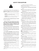
The following illustrations show the various safety decals that are located on the machine. A brief explanation is shown to help the operator understand the meanings of these decals. Read Owner’s Manual and Quick Reference Decal before attempting to operate this machine. Whirling blades! Keep hands and feet away. Beware of thrown objects. Hot surface! Keep shields or covers in place while machine is in operation. Keep hands away from rotating pulleys and belts.
OPERATION WalkBehind Controls 7 11 2a 2b 15 10 19 8 3 10 16 6 8 5 4 10 7 9 14 1 18 13 8 10 17 12 1. 2a. 2b. 3. 4. Ignition Switch Throttle/Choke Lever Throttle Serial number plate Neutral Lock Lever 5. 6. 7. 8. 9. H-bar handle Deck clutch switch Operator presence control lever Anti-scalp wheels Hour meter 10. 11. 12. 13. 14. Height adjusting pins Hydraulic reservoir Discharge chute Pump clutch chain Fuel tank 15. 16. 17. 18. 19.
Operator presence control levers Slot Chain Operator presence control levers in disengaged position H-bar handle Figure 3-3 Figure 3-5 Operator presence control levers WARNING: The safety interlock system must not be disconnected or bypassed. NOTE: The machine is equipped with operator presence control switches.
Bar Steering FRONT OF TRACTOR FACES THIS DIRECTION Figure 3-7 that disengages the pump clutch belt. When the belt is key when engine starts. disengaged, the engine will start easier in colder tempIMPORTANT: The engine starter should not be eratures. operated for periods longer then 30 seconds at a time.
DANGER: When traveling in reverse rotate handle forward gently and avoid sudden movement. Any sudden movement could cause the front of the mower to come off of the ground resulting in possible loss of control. 4. Place the neutral lock in the locked (rear) position and the deck clutch switch disengaged (down) position. The engine should continue to run without the operator presence control switches engaged. 5.
the following: 1-1/4”, 1-3/4”, 2-1/4”, 2-3/4”, 3-1/4” or 33/4”. If the two spacers are placed between the clevis pin and the deck carrier height adjusting bracket (Fig. 3-9), then the deck height will be set at one of the following: 1”, 1-1/2”, 2”, 2-1/2”, 3”, 3-1/2” or 4”. Height adjusting pin Mower deck operation Ball joint DANGER: Never attempt to make any adjustments to the mower deck while the engine is running or with the deck drive clutch engaged.
Continue at an angle until the wheel clears and then pivot the opposite wheel around. The following list is not all inclusive. When turning on soft wet turf, keep both wheels rolling either forward or backward. Pivoting on one stopped wheel can damage turf. This is especially important when mowing. Unit performance is maximum when the throttle is set at full rpm. This gives maximum power to the drive wheels and deck when needed. Use the H-bar handle to control ground speed rather than engine rpm.
MAINTENANCE MAINTENANCE LOCATOR CHART 12 10 13 37” Deck Viewed from top of unit 6 7 13 1 17 17 3 11 13 20 4 5 13 2 12 15 1. 2. 3. 4. 5. 6. 7. 8. 9. 10. 11. 12. 13. 14. 15. 16. 17. 18. 19. 20.
SERVICE AT INTERVALS INDICATED Verify safety start interlock system Visually inspect unit for loose hardware and/or damaged parts Visually inspect tires Check oil level, engine (1) Clean air intake screen Check fuel level Blades - sharpen & securely fastened Discharge chute - securely in place & in lowest position Replace air cleaner paper element (7) Grease gauge wheel bearings Change engine oil filter Change engine oil and filter (4) Check battery connections Clean cylinder and head fins (a) Check battery
Torque values after every 500 hours of use or annually, whichever occurs first. Each spindle shaft is equipped with a grease zerk located on under the deck. Use no more than one or two ounces of SAE multi-purpose grease, (1 to 2 pumps on an average grease gun). Do not force lubricant in to grease zerks. Bearings are sealed and do not require much lubricant. WARNING: Particular attention must be given to tightening the drive wheel lug nuts and wheel motor nuts.
Fuel tank Cap lock Hydraulic reservoir Hydraulic oil filter Cap screw Figure 4-4 Figure 4-5 (Fig. 4-3). Turn and pull up on the filler cap. Fluid level should touch the bottom of screen under filler cap. Use only SAE 10W40 SG, SF/CC, CD service motor oil. Change hydraulic system filter element (Fig. 4-4) after first 50 hours of tractor operation, then replace filter and oil in reservoir every 500 hours thereafter. When changing hydraulic oil use approximately 1/2 of a 7 oz.
Engine oil filter Fuel tank Figure 4-6 Figure 4-8 Fuel filter Engine drain plug Figure 4-7 Fuel system Figure 4-9 WARNING: Observe usual fuel handling precautions; do not smoke while refueling, do not fill tank with engine running or while engine is hot; allow engine to cool before storing machine inside a building, keep fuel away from open flame or spark and store machine away from open flame or spark if there is fuel in the tank. Read and observe safety precautions at front of this manual. The 5.0 U.
operation, per the engine manufacturer’s recommendations after that. If tractor is being operated in extremely dirty conditions, then it is recommended oil be changed more frequently. The oil filter is located on the left side of the engine. Fig. 4-8 The oil drain is located on the right side of the engine. Fig. 4-9 Engine air filter Models 925644, 925651, 925669, 925677, 926238, 926246 Perform engine air filter maintenance per the respective Engine Owner’s manual. Fig.
elements used on gasoline engines may cause some individuals to opt for a less expensive part. The filter element must be sufficient size and construction to withstand stresses, caused by rapid cycling of the air volume demanded by the engine, without cracking or tearing under fatigue and pressure (especially diesel engines). Therefore, Hustler Turf Equipment and the engine manufacturers have carefully selected a reliable filter designed to fit the needs of the engines.
new belt, or one in good condition, should never run against the bottom of the groove. Replace the pulley when this is the case, otherwise belt will lose power and slip excessively. Never pry a belt to get it on a pulley as this will cut or damage the fibers of the belt covering. Keep oil and grease away from belts, and never use belt dressings. Any of these will destroy the belt composition in a very short time.
Bushing Height adjusting pin Resharpening Pattern Do not sharpen to original pattern (below). It is easier to get a straight cutting edge following the resharpening pattern shown above.
ADJUSTMENTS Introduction For engine torque values, see engine owner’s manual. For all other torques refer to the parts manual for standard torque chart. WARNING: Unless specifically required, DO NOT have engine running when servicing or making adjustments to the unit. Place H-bar handle in the neutral position, engage neutral lock lever, and remove ignition switch key. Repairs or maintenance requiring engine power should be performed by trained personnel only.
Neutral lock control lever Neutral adjust stop Bolts Torsion spring tang Neutral lock plate Figure 5-4 Steering linkage shown in the walking (low range) mode Pump linkage rod end Rear pump lever hole (Do not use) Figure 5-2 not making contact with the floor. 5. Make certain the neutral lock is in the locked (rear) position, reconnect the spark plug wire and start the engine. If either one or both wheels are rotating then the pumps will need to be adjusted for neutral. 6.
End bushing H-bar End bushing Lock nut Washer H-bar tube Operator presence control lever Bushing Figure 5-6 come with practice and experience. Forward and reverse speed control is achieved by rotating the H-bar in the corresponding rotation. It is important that the H-bar rotate freely. If it does not, it may need to be cleaned or adjusted. To adjust: Loosen the lock nuts clamping the end bushings (Fig. 5-6). They may have been overtightened.
should be such that the belt does not slip under normal operating load conditions, assuming the belt is not excessively worn or damaged. As belt stretches and wears in, adjustment may become necessary. To increase belt tension, move the spring chain one (or more) link(s) at the anchor bracket (Fig. 5-11). Installed spring length should be 4.70" ± .3" (11.9 cm ± .76 cm) originally with adjustments of .60" (15.2mm) per chain link. Fig.
WalkBehind. (Fig. 5-15) This anti-scalp kit is recommended to minimize scalping when mowing on rough uneven terrain. After setting the cutting height, adjust the anti-scalp wheels so they extend below the deck but do not contact the ground. They should always be at least 1/4” to 3/4” (.6 cm to 1.9 cm) below the deck. With the unit sitting on a flat level surface, the wheel position can be adjusted up or down as needed from 3/4” to 1-3/4” (1.9 cm to 9.5 cm) below the blade surface.
TROUBLESHOOTING The majority of operating problems that occur with a system can be traced to improper adjustments or delayed service. A consistently applied preventative maintenance program, as outlined in the maintenance section of this manual, will prevent many problems.
STORAGE 4. Drain fuel tank and run the engine until it stops from lack of fuel. Gasoline evaporates if left in carburetor for long periods, forming gum and varnish deposits in carburetor. These deposits will cause engine flooding and loss of power. 5. Remove and replace fuel filter if not done in previous 100 hours. 6. Clean exterior surface of engine. Spread a light film of oil over any exposed metal surfaces of engine that are subject to corrosion. 7.
PRODUCT LITERATURE Hydraulic pump This section contains sources of additional literature concerning your tractor. Literature should be ordered from your Hustler dealer, or direct from indicated source. Power to wheel motors is supplied by two Hydro-Gear BDP10 hydraulic pumps. For more information: Hydro-Gear Customer Services 1411 So. Hamilton Street Sullivan, IL 61951 Phone: 217-728-2581 NOTE: For parts information on your unit, refer to the Hustler Hydro WalkBehind Parts Manual (Hustler P/N 778837).
TECHNICAL SPECIFICATIONS ENGINE SPECIFICATIONS Kawasaki Horsepower 15 No. of Cylinders 2 Displacement 30.1 CU IN Compression Ratio 8.5:1 Max. Torque 25.5 FT LBS @ 2400 RPM Starter Recoil or Electric Fuel Unleaded gasoline with octane rating of 87 or higher. Fuel Filter Replaceable, automotive-type. Cooling Air cooled. Flywheel fan. Governor Mechanical. TRACTION DRIVE SYSTEM: Type Dual hydrostatic. Individual pumps power two direct-drive wheel motors. Hydrostatic system operates on 10W40 motor oil.
INDEX PAGE Adjustment introduction...................................................5-1 Anti-scalp wheels .............................................................5-4 Belt replacement...............................................................4-7 Burnishing the electric clutch...........................................4-7 Cold weather pump clutch ...............................................3-3 Controls ............................................................................3-1 Decals.........