Hustler® Dash™ Operator’s Manual 200 South Ridge Road Hesston, Kansas 67062 607203 REV B
WARNING The engine exhaust from this product contains chemicals known to the state of California to cause cancer, birth defects or other reproductive harm. NOTICE OF REQUIREMENT OF SPARK ARRESTER MUFFLER This equipment may create sparks that can start fires around dry vegetation. California Public Resources Code Section 4442.
TABLE OF CONTENTS General Information . . . . . . . . . . . . . . . . . . . . . . . . . . . . . . . . . . . . . . . . 1-1 To the New Owner . . . . . . . . . . . . . . . . . . . . . . . . . . . . . . . . . . . . . . 1-1 Using this Manual. . . . . . . . . . . . . . . . . . . . . . . . . . . . . . . . . . . . . . . 1-1 Warranty Registration . . . . . . . . . . . . . . . . . . . . . . . . . . . . . . . . . . . 1-1 Model and Serial Number . . . . . . . . . . . . . . . . . . . . . . . . . . . . . . . .
Belts . . . . . . . . . . . . . . . . . . . . . . . . . . . . . . . . . . . . . . . . . . . . . . . . . . 4-3 Mower Blades . . . . . . . . . . . . . . . . . . . . . . . . . . . . . . . . . . . . . . . . . . 4-4 Seat Adjustment. . . . . . . . . . . . . . . . . . . . . . . . . . . . . . . . . . . . . . . . 4-6 Steering Control Lever Adjustment . . . . . . . . . . . . . . . . . . . . . . . . 4-6 Maintenance Locator Chart . . . . . . . . . . . . . . . . . . . . . . . . . . . . . . 4-8 Maintenance Record . . . .
GENERAL INFORMATION This manual applies to the following Hustler® Turf Equipment equipment lines: Hustler® Dash™ Since operating conditions vary considerably, all conditions cannot be addressed individually. Through training and experience, operators should develop safe operating practices suitable to most conditions. Directions used in this manual, for example RIGHT or LEFT, refer to directions when in the operator position and facing forward, unless otherwise stated.
Parts and Service Use original Hustler® replacement parts, or parts that are equivalent in overall performance, that are available from your local Hustler® Dealer. For prompt, efficient service, always provide the following information when ordering parts: 1. Correct part description. 2. Correct part number. 3. Correct model number. 4. Correct serial number. All arrangements for warranty repair and service must be handled through an authorized Hustler® Dealer.
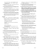
SAFETY PRECAUTIONS Incorrect usage of this equipment may result in severe injury or death. Personnel operating and maintaining it should be trained in its proper use. They should read this manual completely and thoroughly before attempting to set-up, operate, adjust, or service this equipment.
cleaning. Use a stick to clear a plugged discharge area. Never use your hand! • Do not wear radios or music headphones while operating this mower. Safe operation requires your full attention. Always wear safety goggles or safety glasses with side shields when operating this mower. Do not operate the mower if you are fatigued, sick or while under the influence of alcohol or drugs, if you are pregnant or under 18 years old.
Using a Ramp Exercise extreme caution when loading and unloading a mower onto a truck or trailer with a ramp. Use only a single, full width ramp; do not use individual ramps for each side of the unit. Having a full width ramp provides a surface for the mower frame to contact if the unit starts to tip backwards. It also reduces the risk of a wheel going off and the mower tipping over. Do not exceed a 15 degree angle between the ramp and the ground or between the ramp and the trailer or truck.
Another consideration to safe mowing on slopes is to be aware of what is located at the bottom of the slope. Extreme caution should be used when there is a hazard located at the bottom of the slope. Some examples are: • Park the mower on level ground. • Water; i.e. lake, river • Lower the deck. • Cliffs, retaining walls • Stop the engine. • Roads, highways • Remove the ignition key. • Buildings • Disconnect the negative battery cable.
Exercise caution when releasing spring tension from any of the belt idlers or when working with any of the deck lift components. • Do not drink the battery electrolyte. Do not touch hot parts of machine. • Hydrogen gas forms inside the battery. This gas is both toxic and flammable and may cause an explosion if exposed to flame. Always disconnect the negative (black) battery cable(s) before disconnecting the positive (red) cable(s).
It is the owner’s responsibility to make certain that the operators and mechanics read and understand all decals before operating this machine. • Keep gasoline away from open flame or spark and store machine away from open flame or spark or pilot light such as on a water heater or appliances. WARNING • Refuel outdoors. Never refuel or drain the gasoline from the machine indoors. • Never attempt to start the engine when there is a strong odor of gasoline fumes present. Locate and correct the cause.
DANGER: Rotating blades, pulleys & belts • Part Number 602041 Keep a safe distance from the machine. 602041 • WARNING: Hot surface! • 601837 Part Number 601837 Keep shields and covers in place while machine is in operation Keep hands, feet and clothing away from rotating pulleys and belts. Part Number 600899 If you lose steering control while operating the machine, place the steering control levers in the park brake position immediately.
DANGER: Battery Hazards! Part Number 601815 601815 • • • Avoid skin contact with battery acid • Do not overfill battery. Electrolyte may overflow and damage paint, wiring or structure. When cleaning the battery, use soap and water. Be careful not to get soap and water into the battery. Use soda mixed in water to clean corrosion off the terminals. Always wear eye protection when checking the battery, acid can cause serious injury to skin and eyes.
H D E C L A M G F B 607065 J K A. B. C. D. E. F. G. H. I. 607203 Part Number 607065 Fast Slow Choke Mower blade engage/disengage switch Ignition switch—insert key OFF ON Engine start position Wear ear protection, eye protection and safety shoes when operating this equipment. J. K. L. M. 2-9 I Read Operator’s Manual before attempting to operate this machine. Before starting the engine: • Read Owner’s Manual. • Disengage mower blades. • Place control levers in park brake position.
Part Number 601981 WARNING: Read Operator’s Manual and decals before attempting to operate this machine. WARNING: Roll over! • Operate a safe distance (minimum of 10 feet) away from drop-offs, retaining walls, drainage ditches, embankments, water, and other types of hazards to avoid a wheel dropping over the edge or to avoid the ground from breaking away. WARNING: Back over! • • Do not carry passengers. Always stop machine if someone enters the area.
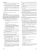
Slope Guide Use this diagram when determining the degree of slope to be mowed. E (15o) Slope Guide Lines D (10o) Line B C (5o) Line A 1. Hold this sheet of paper in front of you. Make sure that Line A is horizontal. 2. Align Line B with a vertical surface such as pole, tree or building. 3. Fold the paper along the slope guide lines (C, D or E). 4. Align the closest slope guide line with the ground slope. This will give you a close estimation of the ground slope to be mowed.
REV B 2-12 607203
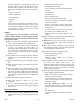
OPERATION Safe Operating Practices Refer to the Safety Precautions section of this manual for operational and personal safety information. Control Panel A D E B E. Hour meter C Figure 3-2 A. Deck clutch switch B. Ignition switch Controls C. Throttle D. Choke A. Figure 3-1 Deck clutch switch (Figure 3-1) — this switch engages the deck. Pull the switch up to engage and push the switch down to disengage the clutch.
Shown with steering control levers in the neutral position A A B. Deck lift pedal Figure 3-5 6. If the engine fails to stop when: • the deck clutch switch is up, or A. Steering control lever • one or both of the steering control levers is in the up (out of neutral position), and Figure 3-3 • the operator is off the seat, then Shown with steering control lever in the park brake position • check the function of the seat switch.
NOTE: The operator’s seat is equipped with a separate safety switch. If for any reason the operator should become unseated when the steering control levers are not in the park brake position (park brake switches are disengaged) or the deck clutch switch is engaged, the engine will stop. Place the steering control levers in the neutral position, to release the park brakes, so that the mower can be moved. Do not tow the machine. Move it by hand or use a winch to load onto a trailer for transporting.
Zero radius turn, move one steering control lever forward and the other steering control lever back of neutral. This allows the drive wheels to counter-rotate. Figure 3-7 FRONT OF MOWER FACES THIS DIRECTION To stop or decrease speed, move steering control levers to neutral. When going forward pull back gently on steering control levers. When going in reverse push forward gently on steering control levers.
Operating Suggestions THREE POINT TURN DANGER An inexperienced operator should not mow on slopes or on uneven terrain. Before attempting normal speed operation an inexperienced operator should: • be thoroughly familiar with the proper use and operation of the equipment. • read the manual completely and thoroughly. ft Le rol nt co ever l If you lose steering control while operating the machine, place the steering control levers in the park brake position immediately.
DANGER DANGER Never work with blades while the engine is running or deck clutch switch is engaged (on). Always place the deck clutch switch in the disengaged position, place steering control levers in the park brake position, turn the engine off and disconnect the negative battery cable. Never attempt to make any adjustments to the mower deck while the engine is running or with the deck drive clutch engaged. Mower blades cannot be seen and are located very close to the deck housing.
• no load on the blades. located in the “G” slot, the deck height is at its highest mowing position or transport mode. After clutch engagement, adjust the deck cutting height to the desired level, if necessary, and advance the engine throttle to full rpm. To adjust the cutting height, step on the deck lift pedal and insert the adjusting pin into the desired cutting height hole. Release the deck lift pedal.
REV B 3-8 607203
MAINTENANCE & ADJUSTMENTS Safe Servicing Practices Torque Values Service Introduction Regular maintenance is the best prevention for costly downtime or expensive, premature repair. The following pages contain suggested maintenance information and schedules which the operator should follow on a routine basis. For more detailed information order the correct Parts Manual and General Service Manual for your unit. Refer to the Product Literature section of this manual for more information.
Master In-Line Fuse • canister mounting brackets These mowers have a master in-line fuse in the electrical system. This is the main fuse to protect the complete electrical system. It is located under the seat platform and next to the solenoid.
WARNING Overfilling the fuel tank may cause the following: 3. Position a suitable oil drain container under the machine below the end of the oil drain hose. 4. Twist the cap on the end of the hose and pull the cap open to allow the oil to drain. Allow 10 minutes for engine oil to adequately drain. Figure 4-4 5. After the oil is drained, place the cap back on the end of the hose and close it by turning it clockwise. 6. Clip the oil drain hose onto the engine bracket. 7.
Replace any blade which is bent, cracked or broken. • severe cuts • tears Always check for blade damage: WARNING • separation • weather checking • cracking • burns caused by slipping. WARNING Slight raveling of belt covering does not indicate failure, trim ravelings with a sharp knife. • if mower strikes a rock, branch or other foreign object during mowing! • or if an abnormal vibration occurs while operating. Make all necessary repairs before resuming operation.
Do not re-use spindle bolts which have stripped, worn or undercut threads. Torque bolts on spindles to 48 ft-lbs (65 N•m) when reinstalling blades. Comparison of Warped and Straight Blades B WARNING A C Failure to correctly torque the bolt may result in the loss of the blade which can cause serious injury. IMPORTANT: The blade sail (curved part) must be pointing upward toward the inside of the deck to ensure proper cutting. A. Warped blade — replace B. Straight blade C.
A A A B A A A. Cap screws C Figure 4-9 align the holes in it with the holes in the lower lever. Re-install the cap screws and tighten. A. Spindle shaft face B. Boss The steering control levers should be adjusted so that they align with each other when in the neutral position. C. Blade Figure 4-8 Seat Adjustment A The seat on the Hustler® Dash™ mower can be adjusted forward and rearward. 1. Pivot the seat platform up and forward. 2.
Maintenance Schedule Refer to Figure 4-11, Figure 4-12, and Figure 4-13 WEEKLY OR 40 HOURS SERVICE AT INTERVALS INDICATED * ANNUALLY OR 100 HOURS Verify safety start interlock system Prior to each use Visually inspect unit for loose hardware and/or damaged parts Prior to each use Visually inspect tires Prior to each use Check oil level, engine (1) Prior to each use or every 4 hours Clean air intake screen (6) Prior to each use or every 4 hours Check fuel level Prior to each use Blades - shar
Maintenance Locator Chart 7 1 4 Figure 4-11 6 10 3 9 1. 2. 3. 4. 5. 6. 7. 8. 9. 10. 11. 12.
Figure 4-13 1. 2. 3. 4. 5. 6. 7. 8. 9. 10. 11. 12.
Maintenance Record Date: Date: Maintenance/Service Performed: Dealer: Maintenance/Service Performed: Dealer: Hour Meter Reading: Hour Meter Reading: Date: Date: Maintenance/Service Performed: Dealer: Maintenance/Service Performed: Dealer: Hour Meter Reading: Hour Meter Reading: Date: Date: Maintenance/Service Performed: Dealer: Maintenance/Service Performed: Dealer: Hour Meter Reading: Hour Meter Reading: Date: Date: Maintenance/Service Performed: Dealer: Maintenance/Service Performed:
TROUBLESHOOTING The majority of operating problems that occur with a system can be traced to improper adjustments or delayed service. A consistently applied preventative maintenance program, as outlined in the Maintenance section of this manual, will prevent many problems. The following chart is designed to help you locate a problem by suggesting probable causes and the recommended solutions.
REV B 5-2 607203
When storing the unit at the end of the mowing season, the mower, engine, and battery should have the following items serviced before storage. If the mower has been stored for an extended period of time, follow the new season preparation steps before beginning operation. WARNING STORAGE To prevent carbon monoxide poisoning, operate the engine in a well ventilated area only. General mower preparation for storage IMPORTANT: Wash the machine with a mild detergent and water.
WARNING control levers. Stop engine and check for oil leaks, loose fittings and so forth. REV B At start of new season always check that fresh oilhas been added to machine. If oil is drained at season’s end and not replaced, engine damage will result. 6-2 5. Tighten any bolts that have loosened and make sure all hair pins, cotter pins and clevis pins are in place. 6. Install all safety shields and review safety precautions listed in this manual. 7. Check and inflate tires to 8–12 psi (55–83 KPa).
PRODUCT LITERATURE If you would like to view or print a copy of the product manuals (Operator’s Manual, Parts Manual, or General Service Manual) for these mowers go online to www.hustlerturf.com. Contact your local Hustler® dealer if you require another engine manual.
REV B 6-4 607203
INDEX PAGE PAGE Battery Service Precautions ............................................. 2-5 Mower Operation ................................................................ 3-3 Belts ..................................................................................... 4-3 New Season Preparation ................................................... 6-1 Children ............................................................................... 2-4 Operating Suggestions ...................................
INDEX REV B PAGE i-2 PAGE 607203