
Operating Guide

604856 3-7 REV P
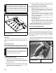
Flex Forks
®
New Flex Forks
®
require a brief break-in period. Refer to the
Maintenance and Adjustments section of this manual for more
details.
Deck Clutch Operation
Before beginning operation, check to make sure the deck
clutch switch is engaging and disengaging the blades properly.
To check the deck clutch switch:
1. Start the engine and engage the deck clutch.
2. With the deck clutch switch up (clutch engaged) and
the engine running, listen to confirm that the mower
blades are rotating.
3. Now, push the deck clutch switch down (clutch disen-
gaged), and with the engine running, listen to confirm
that the blades have stopped rotating.
4. If the mower blades continue to rotate with the deck
clutch switch down, discontinue operation immedi-
ately and contact your Hustler
®
Dealer.
Follow these procedures to maximize clutch life.
1. Engage the clutch only when the throttle is set at
approximately 2/3 throttle and there is no load on the
blades. After clutch engagement, advance the engine
throttle to full rpm.
Engaging the deck clutch at high engine rpm or when
under heavy load (in tall grass, for example) can cause
belts and/or electric clutch to slip, resulting in premature
wear or possible damage.
2. Disengage the clutch only when the throttle is set at
less than 1/2 throttle.
Never disengage the clutch with the engine running at
high rpm. Setting the throttle to less than 1/2 throttle
when disengaging the clutch will help extend clutch life.
Warranty will not be allowed for deck clutches that fail due
to improper engagement and disengagement practices.
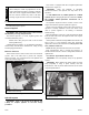
Deck Cutting Height Adjustment
Deck cutting height is adjustable in 1/4” (6.4mm) incre-
ments.
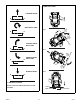
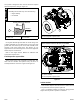
Step on the deck lift pedal and latch the transport lever in
the deck transport position. Pull the adjusting pin out of the
hole that it is in and insert it into the desired cutting height
hole. Step on the deck lift pedal to release the transport
lever. Figure 3-11
Step on the deck lift pedal and raise the deck to its highest
position and latch the transport lever in place when trans-
porting the unit. Figure 3-11
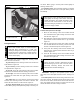
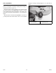
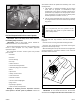
Discharge chute may vary from this illustration
A. Discharge chute
Figure 3-10
Never attempt to make any adjustments to the
mower deck while the engine is running or with the
deck drive clutch engaged. Mower blades cannot
be seen and are located very close to the deck
housing. Fingers and toes can be cut off instantly.
Make sure that the area around and under the deck
is clear and that there are no bystanders in the
immediate area before proceeding.
A
DANGER
WARNING
A. Transport lever
B. Cutting height holes
C. Pin
Figure 3-11
B
A
C