
Operation Manual


10
CHANG E S AND T YPI N G ERRORS RESERVED
CHANG E S AND T YPI N G ERRORS RESERVED CHANG E S AND T YPI N G ERRORS RESERVED
4. assembly
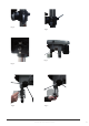
• Place the column on the base and align the holes in the column support with the holes in the base (fig. 1).
• Secure the column with the bolts and washers.
• Take off the collar and the rack. (fig. 2)
• Install the bracket together with the rack.
• Install the collar and tighten firmly (fig. 3)
• Install the bracket handle and clamp bolt. Tighten the handle with the set screw and tighten the clamp bolt
(fig. 4 and 5).
• Install the table and clamp it with two bolts (fig. 6).
• Carefully put the head frame over the column and slide it into position. Align the head frame with the table and
base. Fix the set screws on the right side of the head to lock it into position.
• Screw the knob on each feeding handle, install them into the hub of the pinion shaft (fig. 7).
• Insert the arbour into the spindle and pull the feeding handle down to press it inward.
• Open the chuck jaws completely by turning the attached chuck key counter-clockwise. Put a piece of scrap
wood on the table to protect the chuck nose.
• Pull the feeding handle down and press the chuck against the scrap wood until the chuck is forced into the
spindle (fig. 9).
• Install the knob and screw of the upper pulley cover (A, fig. 10).
Clean the taper for the drill chuck with a clean cloth.
5. adjUsTmenT
5.1 Table adjUsTmenT
Height adjustment:
To adjust up or down, loosen the clamp bolt and then adjust the table to the desired position by turning the table
bracket handle (A, fig. 11).
360
O
swing:
Loosen the clamp bolt (C) and then swing the table to the appropriate position and retighten the clamp bolt (fig. 12).
5.2 feed depTh adjUsTmenT
Loosen the clamp bolt and move to the desired depth. Then, re-tighten the clamp bolt (fig. 13).
5.3. speed adjUsTmenT
Figures 14, 15, 15A and 15B
1. Pull the plug.
2. Open the pulley case and loosen the belt tension lock handle.
3. Choose the speed for the drilling operation and move the belt to the correct position.
4. Push the motor backward until a moderate belt tension is acquired. Re-tighten the handle again.
Diameter of
drill
Cast steel Tool steel Cast iron Mild steel Alum. and
copper
Cutting speed
m/min ft/min m/min ft/min m/min ft/min m/min ft/min m/min ft/min
12 40 18 60 24 80 30 100 60 200
mm Inch Speed range based on drilling diameter and cutting speed
2 1/16 1910 2445 2865 3665 3820 4890 4775 6110 9550 12225
3 1/8 1275 1220 1910 1835 2545 2445 3185 3055 6365 6110
5 3/16 765 815 1145 1220 1530 1630 1910 2035 3820 4075
6 1/4 610 610 955 915 1275 1220 1590 1530 3180 3055
8 5/16 480 490 715 735 955 980 1195 1220 2390 2445
10 3/8 380 405 570 610 765 815 955 1020 1910 2035
11 7/16 350 350 520 525 700 700 870 870 1740 1745
13 1/2 300 305 440 460 590 610 735 765 1470 1530
16 5/8 240 245 360 365 480 490 600 610 1200 1220
19 3/4 190 205 285 305 380 405 480 510 955 1020