D R I L L I N G - M A C H I N E S HU 30FP SUPER VARIO
T able of contents 1. General safety rules for all machines 2. 3. 3.1 4. 5. 6. 7. 7.1 7.2 7.3 7.4 7.5 7.6 7.7 8. 9. 10. 11. 12.
Drilling machine HU 30FP Super Vario 1. General safety rules for all machines N.B.: Read the instructions carefully in order to avoid any problems. As with all machinery there are certain hazards involved with operation and use of this machine. Using the machine with respect and caution will considerably lessen the possibility op personal injury. However, if normal safety precautions are overlooked or ignored, personal injury to the operator may occur.
2. Additional safety rules Always keep in mind that: • the machine must be switched off and disconnected from the power supply during maintenance and repairs, • clamped workpieces may only be measured when the machine is switched off. Never lean over the machine, mind loose clothing, ties, jewellery etc. and wear a cap. Do not remove safety devices or guards. Never use the machine while a guard is open. Always use safety glasses for machining rough materials.
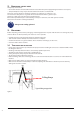
4. Features Model HU 30 FP Super Vario Drilling capacity 30 mm Spindle taper MT3 Distance column-spindle 209 mm Drilling depth 125 mm Speed range 100-2500 (variable) Max. distance spindle-table 750 mm Column diameter 92 mm Table dimensions 395 x 285 mm Motor power 1,5 kW Lifting Straps Lifting Straps Typical lifting strap position. Weight 198 kg Typical lifting strap position. 1-3. Setting the machine instruction: Voltage 400 V 1.
. Main parts Pulley cover Motor Head Handle v belt tension Emergency stop Feed handle Drill head Chuck guard Column Rack Table Handle table height adjustment Base Figure 4 6 CHANGES AND T YPING ERRORS RESER VED
C. Stop Button A.min-1 or /min (R.P.M.) Indicator JS-834V or JS-840VB 7. Control panel JS-834V JS-30VP F A B. D. Speed Control Switch Cutting Liquid Control Switch A: Speed display JS-30P/30VP) B:(For Start button C. Fault light Stop button E.C:D:Emergency Stop Button(For CE) Coolant on/off switch E: Emergency D.Start Buttonstop F: Speed control switch F. Speed Control Switch E. Emergency Stop Button(For CE) G.Jkm CamAdjustment Switch (high/low) F.Feed Depth BG. Drill / Tap Switch 1.
7.Adjust work table position (1)Firstly, loose the clamp handle in left hand(Figure 19) 1. Adjustment limit (2)Then swing the table handleoftofeeding properly position. (Figure 20) 7.2 W ork table adjustment To prevent unwanted penetration (3)Finally tight the clamp handle.(Figure 19) to work piece, the feeding limit shall be set by adjusting the appropriate position of feeding depth fixing button as long as the distance between the end of tool and top surface if work piece is measured. A.
4. Adjustment of feeding limit 7.4 ToDprevent rill depth adjustment unwanted penetration to work piece, the feeding limit To prevent drillby from going too into the work piece, can setdepth the shall the be set adjusting thedeep appropriate position ofyou feeding feeding limit by adjusting the position of the feed depth knob (A, figure 13). fixing button as long as the distance between the end of tool and top surface if work piece is measured.
JS-30series 7.6 V belt adjustment A headstock. wdstock. sign to get belt tension. nnsion. to get belt tension. A n lead bolt (parts no. 22-S2) on both side of headstock. Pull belt n. B A epositioning and then move belts to correct groove to acquire d bolt (parts no. 22-S2) on both side of headstock. Pull belt See following speed chart for reference. ioning and then move belts to correct groove to acquire 1. Loosen knob B on both sides of headstock. Figure 14for reference.
8. Troubleshooting Switch off power and remove plug from power source outlet before trouble shooting. Problem Solution 5-1. Feed Shaft Spring Tension: Drill is caught in the work piece and the spindle 1. Push the emergency button hasThe stopped Turn offduring the power feed shaft return spring is adjusted at thefactory; 2. however, the life of the drill pressyou may 3.
Tapping capacity ---------- ---------- Spindle taper M.T.#3 M.T.#3 Turn the machine off and disconnect it from the mains before maintenance or repairs are performed! Spindle travel 125mm 125mm • Take out the 4 screws and take away the 50 cover Hz (figure 17). 105 – 2650/min Spindle (rpm) 2500/min • Wipe off any oil on speed the spring lock cover so it does not slip when you hold the cover. Wear100– protective gloves.
11. Control circuit diagram Figure 22 Symbol Part M1 No. M2 M1 KA M2 KA KA1 KA1 VR VR U1 U1 RPM RPM TR TR FU FU SQ1 SQ1 SQ2 SQ2 SB1 SB1 SB2 SB2 SB3 SB3 SB4 SB4 Function Component/Object PARTS LIST JS-30V/30VP switch chuck guard MicroMicro Switch Chuck Guard Tech. data Number Ratings/Technical Data Pcs Complies with the following 1,5 kW/400V/1PH 1 standard 0,1 kW/400V/1PH 1.5kW / 400V/ 1Ph 1 EN60204 1 UI 600V/25A 1 0.
12.
JS-30series 1 1A 1B 1C 1D 1E 1F 1G 1H 1-S1 1-S2 1-S3 1-S4 2 2-S1 2-S2 3 5 5A 6 7 8 9 9A 9-S1 14 15 16 16-S1 16-S2 18 18A 18B 18C 18-S1 18-S2 18-S3 18-S4 18-S5 18-S6 18-S7 18-S8 19 20 20A 20B 20-S1 22 22A 22C 22D 22E 22-S1 22-S2 22-S3 22-S4 22-S5 22-S6 22-S7 22-S8 26 27 27-S1 29L 29S 29-S1 BASE WATER TANK BASE COVER PUMP MOTOR 400V ADAPTER CLAMP HOSE WATER TANK COVER HOSE COVER SCREW SCREW SCREW SCREW COLUMN HOLDER BOLT SPRING WASHER COLUMN TABLE BRACKET OIL CUP GEAR GEAR BRACKET WORM TABLE HANDLE HANDLE BO
Our products are frequently updated and improved. Minor changes may not yet be incorporated in this manual. Always state the year of build, type and serial number of the machine in correspondence. Manufacturer and importer assume no responsibility for defects which result from not reading the manual carefully or wrong use of the machine. No rights can be derived from this manual. All rights reserved.
CE DECLARATION OF CONFORMITY (in accordance with supplement II, section 1A of the Machinery Directive) Industrie & Handelsonderneming Huberts bv, Kennedylaan 14, 5466 AA Veghel, the Netherlands, in the capacity of importer, is to be held responsible for declaring that the Huvema machine: Drilling machine HU 30 FP Super Vario which this declaration relates to, is conform the following norms: NEN-EN-ISO 12100:2010, NEN-EN-IEC 60204-1:2006/C11:2010, NEN-EN-IEC 61000-6-1:2007, NEN-EN-IEC 61000-6-3:2007/A1:2011
CHANGES AND T YPING ERRORS RESER VED
CHANGES AND T YPING ERRORS RESER VED 19
14 V1