D R I L L I N G - M A C H I N E S HU 32 SUPER VARIO HU 40 SUPER VARIO
Table of contents 1. 2. 3. 3.1 4. 5. 6. 7. 7.1 7.2 7.3 7.4 7.5 7.6 7.7 7.8 8. 9. 10. 11. 12. 12.1 12.2 12.3 12.
Drilling machines HU 32 Super Vario - HU 40 SuperVario 1. General safety rules for all machines N.B.: Read the instructions carefully in order to avoid any problems. As with all machinery there are certain hazards involved with operation and use of this machine. Using the machine with respect and caution will considerably lessen the possibility op personal injury. However, if normal safety precautions are overlooked or ignored, personal injury to the operator may occur.
2. Additional safety rules Always keep in mind that: • the machine must be switched off and disconnected from the power supply during maintenance and repairs, • clamped workpieces may only be measured when the machine is switched off. Never lean over the machine, mind loose clothing, ties, jewellery etc. and wear a cap. Do not remove safety devices or guards. Never use the machine while a guard is open. Always use safety glasses for machining rough materials.
4. Fthe eatures 4.Slide arbor into the spindle socket whileslowly rotating the drill chuck. The socket hasa rectangular pocket where the tang (or flatportion of the arbor shown in Figure 21) fitsinto. Model HU 32 Super Vario HU 40 Super Vario Drilling 32 mallet, mm 4022. mm 5.
. Main parts Pulley cover Motor Head 1-4.Major Parts: A Handle v-belt tension B Emergency button O P Drill head Protective cover N Feed handle C Column Rack M Table D Handle for table height adjustment 1-4.
D.Start Button E. Emergency Stop ButtonIndicator (For CE) A.min -1 or /min (R.P.M.) A: Speed indicator B: Speed control switch F.Feed Depth Adjustment C:B. Warning light Control Switch Speed 7. Control panel JS-834V or JS-840VB D: Start button E: Emergency button F: Feed depth adjustment G: Drill/tap switch H: Stop button I: Control switch coolant liquid G. Tap Switch C.Drill Fault/ light H. Stop Button D.Start Button JS-834V I.E.Cutting Liquid Control Switch Emergency Stop Button (For CE) 1.
shownin Figure 12.) If you want to continue to operate, just press down grip handle.(as 7.2 Tapping shownin Figure 13.) LooseLoose Figure 8 13 Figure 7 12 Figure Figure Figure 17 Figure 18 Figure 17 Figure 18 6.Please open water outlet valve andshall adjust proper volume after power supplying. Fig 18 by a micro 3. machines Protect safety guard beaallocated in a outlet proper position in operation. It Fig isyou controlled .
Figure 14 Figure 15 Figure 16 You can position the vice by loosening the set screw (figure 14). Tighten the set srew when the vice is in the correct position. 10 4. Adjustment of feeding limit Loose to work piece, the feeding limit To prevent unwanted penetration shall be set by adjusting the appropriate position of feeding depth fixing button as long as the distance between the end of tool and top surface if work piece is measured. Figure 14 A.
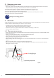
Drilling- series Lpa= 64 Operator position dB(A) 13 7.7 V belt adjustmentJS-834 / JS-834V / JS-840VB A B 1. Loosen knob B on both sides of headstock. Figure 16 2. JS-834V Pushknob handle A forward as arrow sign to get belt tension. For • Loosen B on both sides of the headstock. knob B firmly to fix belt tension. • 3.Lock Push handle A forward to increase the belt tension, back to decrease the tension. • Lock knob B firmly again. When speed change is required. Loosen lead bolt (parts no.
8. Troubleshooting Switch off power and remove plug from power source outlet before trouble shooting. Problem Solution Drill is caught in the work piece and the spindle has stopped 1. Push the emergency button 2. Turn off the power 3. Turn the spindle manually counterclockwise to withdraw the tool from the work piece 4. Clean any chips on the work piece. 5. Turn on the power again 6.
Spindle taper M.T.#3 M.T.#3 M.T.#4 Spindle travel 140mm 140mm 145mm Turn the machine off and disconnect it from the mains before maintenance or repairs are performed! Spindle speed (rpm) 105 – 2650/min 80– 2500/min 70– 2000/min • Take out the 4 screws and take away the cover (figure 18). Number of speeds Variable Speeds Variable Speeds 9×2 steps • Wipe off any oil on the spring lock cover so it does not slip when you hold the cover. Wear protective gloves. • Loosen the lock nut (figure 19 and1.
JS-834V/840VB 11. Control circuit diagram Part Part No. Component/ Object Component/Object Type/ 20 PARTS LIST Type/Model Ratings/ Ratings/JS-834V/JS-840VB PCS Complies with Technical PCS Data Complies with the standard Marks of Marks of conformity CS(For ce) General on/off switch ZH-C316 AC 440V16A 1 EN60947 CE KA1 Contactor C-12D AC 440V/24V/12A 1 IEC 947-4-1 CE ULSA KA2 Contactor C-12D AC 440V/24V/12A 1 IEC 947-4-1 CE ULSA TR(For ce) Transformer SL-2930N AC400V/24V7.
SB4 Selection switch (drill/tap) GCS-22 INAAC125V,6A 1 IEC 144 CSA CE LR108205-2 SB5 Emergency stop GLEB-22 INCAC 125V, 6A 1 IEC 144 CSA CE LR108205-2 VFD-E Inverter VFD-E AC 400V / 1.5kW AC 400V / 2.2kW 1 EN 50178 EN 61800-3 CE EMC U2 Braking resistor QSOJ013 200W250Ω 1 VR Speed adjusting knob RV24YN DC 10V 1 M1 Motor main spindle JS-834V JS840VB 1.5kW / AC 400V/3Ph 2.2kW / AC 400V/3Ph 1 M2 Motor pump 8150 0.
8. Drawing and parts list; 12. Parts drawings and lists 12.
12.
12.
12.
No. Description No.
57 Ball bearing 81-S4 Washer 58 Spindle nut 81-S5 Nut 59 Spindle sleeve 86-S1 Snap ring 59A Lock washer 89 V-belt 59-S1 Key (for HU 40 Super Vario) 90 Allen wrench (l) 60 Ball bearing 91 Allen wrench (s) 61 Collar 101 Micro switch bracket 62 Snap ring 101A Micro switch 63 Pulley nut 101B Micro switch board cover 64 Spindle pulley 101C Micro switch wire 64-S1 Pin 101-S1 Screw 65 Taper arbor 101-S2 Screw 66 Drill chuck 101-S3 Lead bolt 67 Drill shifter
110 Steel bar 111 Micro switch plate 111-S1 Screw 111-S2 Washer 112 Micro switch body 112A Micro switch trigger 112-S1 Screw 114 Micro switch 114-S1 Screw 115 Micro switch cover 115-S1 Screw 116 Thrust bearing 117 Tapping sensor 117-S1 Pin 118 Spring 119 Magnet 120 Orientation bolt 120A Spring 120-S1 Screw V105 Vise body V105A Set slider V106 Leadscrew V106A Set slider V107 Moving stand V107-S1 Set screw V107-S2 Set screw V107-S3 Nut V109 Vise handle V
Our products are frequently updated and improved. Minor changes may not yet be incorporated in this manual. Always state the year of build, type and serial number of the machine in correspondence. Manufacturer and importer assume no responsibility for defects which result from not reading the manual carefully or wrong use of the machine. No rights can be derived from this manual. All rights reserved.
CE DECLARATION OF CONFORMITY (in accordance with supplement II, section 1A of the Machinery Directive) Industrie & Handelsonderneming Huberts bv, Kennedylaan 14, 5466 AA Veghel, the Netherlands, in the capacity of importer, is to be held responsible for declaring that the Huvema machines: Drilling machines HU 32 Super Vario - HU 40 Super Vario which this declaration relates to, are conform the following norms: NEN-EN-ISO 12100:2010, NEN-EN-IEC 60204-1:2006/C11:2010, NEN-EN-IEC 61000-6-1:2007, NEN-EN-IEC 61
2014 V1