
Operation Manual


18
CHANGES AND TYPING ERRORS RESERVED CHANGES AND TYPING ERRORS RESERVED
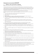
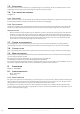
10.2. elecTrical circuiT
Picture I
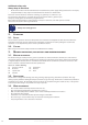
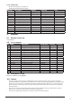
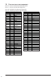
Picture J – control circuit
J1 – Drilling/tapping
J2 – Raising/lowering
J3 – Indicator of power
J4 – Feed clutch
10.2.1. main power swiTch (Qs1)
The main power switch (QS1) is for controlling the power supply. It has opening for safety locking with a padlock.
10.2.2. proTecTion of The main moTor
The main motor is protected by a 3VU1340 auto switch (QF1), which can protect the motor from overload.
10.2.3. proTecTion of coolanT pump
The coolant pump is protected by means of a 3VE automatic switch (QF2).
10.2.4. Tapping operaTion
Tapping operation is controlled by contactors KM1, KM2 and select button SB6. The travel limit of tapping is
controlled by SQ2, SQ3.
When tapping, turn the select button SB6 to position `1’ (‘0’ for driving), turn the LW6B combination switch to
`1’ to start the spindle forward (KM1, KM2 engaged). Hand feed spindle downward until the tool touches the
work piece to be tapped. When the tapping depth is reached, limit switch SQ3 is activated; the spindle rotates in
reverse direction (KM1, KM3 engaged) and the tap withdraws from the workpiece.
When the spindle returns to the highest point, limit switch SQ4 is operated. The spindle rotates forward and one
cycle of operation is finished.
For the next tapping operation, repeat the steps above. For drilling, turn the button SB10 to position `0’.
Warning! The motor turns forward and reverses frequently during tapping, so each operation should not exceed
8 times per minute. Please stop the motor and cool it down when it is hot, otherwise the motor could be burnt
down.
10.2.5. power feeding operaTion
Move the spindle 5-6 mm down and push one of the buttons at the end of the feed levers. The electromagnetic
clutch is engaged, automatic feed starts and the indicator lamp (12) lights. Drilling is stopped by the limit switch
when the desired depth is reached.
If you need to stop the power feed, push button (5) to disengage the electromagnetic clutch.
10.2.6. emergency sTop
During the process of machining, the emergency stop button SB3 can be pushed down for an emergency stop.
When SB3 is pushed down, contactor KM1 loses current and the machine stops. To restart the machine, relieve
the mechanical lock of the button.
10.2.7. Zero volTage proTecTion
Zero voltage protection is provided by contactor KM1. When the power is restored, push button SB4 to engage
contactor KM1 and restart the machine.
10.2.8. work Table elevaTion
Automatic raising and lowering of the work table and its bracket is not possible when the bracket is clamped.
10.2.9. The funcTion of The safeTy guard
The machine can not be started when the safety guard is not in the correct working position.
10.3. insTallaTion of The main moTor
• Engage the gears of the main motor with those of the gear box, tighten the four M14 x 35 hex bolts.
• Connect the main power supply line and ground wire as shown on the electrical diagram (H).