Digital Display Unit HDA 5500 User Manual HDA 5500-1-1-AC-000 HDA 5500-1-1-DC-000 HDA 5500-1-2-AC-000 HDA 5500-1-2-DC-000 Dated 16.06.
HDA 5500 User Manual CONTENTS 1 Introduction European standards compatibility 1.1 3 3 2 Safety instructions 3 3 Functions 3 4 Operating keys 4 5 Selecting and displaying the unit of measurement 4 6 Installation and commissioning 6.1 Mechanical installation 6.2 Electrical connection 6.3 Supply voltage 5 5 5 6 7 Programming 7.1 Adjusting the basic settings 7.2 Overview of basic settings menu 7 7 8 8 Connecting sensors 8.1 HDA 5500 with three transmitters 12 12 9 Digital display 9.
HDA 5500 User Manual 1 Introduction The individual components and the final assembly of the Digital Display Unit HDA 5500 are subject to strict quality controls. Each HDA 5500 is individually calibrated and subjected to a final test. In this way we can guarantee that the unit is fault-free on despatch and conforms to the given specifications. However, if there is a cause for complaint, please return the unit to us outlining the fault.
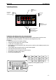
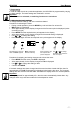
HDA 5500 User Manual 4 Operating elements 4-digit digital display LED display of active switching points Relais 1 Sensor 2 LED display of active sensor 1 2 3 3 4 MODE HDA5500 Display of unit of measurement for sensor 1, 2 or 3 Keys for adjusting the switching points, switch-back points and the menu functions 5 Selection and display of the unit of measurement The operator can select the appropriate unit label from a printed sheet and this is then displayed with background lighting.
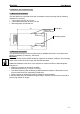
HDA 5500 User Manual 6 Installation and commissioning 6.1 Mechanical installation The HDA 5500 is a control panel unit with a standard mounting housing with the following measures for mounting: • Control panel cut-out: 92 x 45 mm • Control panel thickness: at least 1.25 mm • Mounting depth: at least150 mm Panel clips Panel thickness Clamping guides 6.
HDA 5500 User Manual 6.3 Supply voltage The supply voltage is connected to terminal X1. 12..32 VDC HDA 5500–X–X–DC–000 (see type code label) 85..265 VAC 50 / 60 Hz HDA 5500–X–X–AC–000 (see type code label) After switching on the supply voltage, the unit displays HdA for approximately 2 s. Then the number of the sensor set as the primary display is shown. After a further approximately 2 s the actual value is displayed.
HDA 5500 User Manual 7 Programming In order to adapt the unit to a particular application, the HDA 5500 is programmed by varying the basic settings. The basic settings are combined in a menu. Important: When the menu is activated, no switching functions are carried out. 7.1 Adjusting the basic settings To change the basic settings, the menu must be activated. Procedure for activating the menu: • During normal operation, press the MODE key and hold down for at least 5 s. • MEnu (Menu) is displayed.
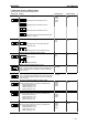
HDA 5500 User Manual 7.2 Overview of basic settings menu Menu point Setting Allocation of switching output 1 to sensor (S.S.1) Switching output 1 allocated to sensor 1 Setting range Default setting SEn.1 SEn.2 SEn.3 DiFF SEn.1 SP Win SP on oFF on 0..99.99 0 0..99.99 0 SEn.1 SEn.2 SEn.3 DiFF SEn.1 SEn.1 SEn.2 SEn.3 DiFF SEn.1 SEn.1 SEn.2 SEn.3 DiFF SEn.
HDA 5500 Menu point User Manual Setting Primary display (PriM) Value which is normally displayed: Setting range Default setting SEn.1 Min.1 ToP.1 SEn.1 Measured value sensor 1 Lowest value sensor 1 Peak value sensor 1 Measured value sensor 2 SEn.2 Min.2 ToP.2 Lowest value sensor 2 Peak value sensor 2 Measured value sensor 3 SEn.3 Min.3 ToP.3 Lowest value sensor 3 Peak value sensor 3 Differential value (sensor 1 - sensor 2) DiFF Min.d ToP.
HDA 5500 Menu point User Manual Setting Reset time (r.TiM) Indicates how long in seconds the last peak / lowest value is displayed for. Setting range Default setting 0..3600 0 5V 10 V mA.r. mA.S. mA.S. 0..0.000 0.0 -999..9899 0 -899..9999 100.0 on oFF on 5V 10 V mA.r. mA.S. mA.S. 5V 10 V mA.r. mA.S. mA.S. Input signal sensor 1 (inP.1) 0..5 V 0..10 V 4..20 mA source 4..20 mA sink Decimal place sensor 1 (dEc.1) No.
HDA 5500 Menu point User Manual Setting Calibration of the sensor zero point (CALi.) Setting range Default setting YES no no SEn.1 SEn.2 SEn.3 diFF SEn.1 MA VoLT VoLT YES no no The actual measurement is saved as the new zero point. This is possible in the range +/- 2.5 % of the display range. is displayed if a calibration has been carried out in the permitted range. is displayed if a calibration has not been possible.
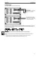
HDA 5500 User Manual 8 Connecting sensors One analogue input for a transmitter or sensor is always available as standard. The particular types of HDA 5500 described here have two further analogue inputs. 8.1 HDA 5500 with three transmitters Connection example for three transmitters (sensors) with a 4..20 mA sink each as input signal, e. g. HDA 5500-1-2-DC-000 with HDA 4746-A-100-000 (refer to chapter 16 Pin connections): HDA 4746-A-...
HDA 5500 User Manual Important: • If the measured value exceeds the upper display range of the HDA 5500, then the measured value can no longer be displayed. The upper display range flashes. • If the measured value is below 1 % of the lower display range, then the measured value can no longer be displayed. The lower display range flashes. 9.2 Special display If a measured value is set as the primary display, then by pressing the or keys the following values can be displayed separately.
HDA 5500 User Manual 10.1.2 Analogue output set to 0..10 V Connection example for analogue output set to 0..10 V: Analog. Out Vout = 0..10 V RLmin 2,000 AGND 10.2 Switching outputs Each switching output consists of a relay, the switching contacts of which can be connected as N/C or N/O. For each switching output, the following parameters can be set during normal operation (see chapter 7.
HDA 5500 User Manual The upper switch point and the lower switch point of a switching window can be individually set for each switching output. The following setting ranges apply: • Upper switch point 1.0..99.5 % of the display range • Lower switch point 0.5..
HDA 5500 User Manual 11 Adjusting switch outputs Procedure for HDA 5500 with switching outputs: • During normal operation, press mode key. • Depending on the settings SP (switch points) or Win (switching window) will be displayed (if no switching outputs are available, noSP (no switch point) will be displayed). • After approximately 2 s the display returns to normal operation. Note: If the mode key is pressed for longer than approximately 5 s, then the Basic Settings Menu will be activated! 11.
HDA 5500 • • User Manual 5500 with four switching outputs Hi.3 (upper switch point 3), Lo.3 (lower switch point 3), Hi.4 (upper switch point 4) and Lo.4 (lower switch point 4) are also shown. If an upper switch point or a lower switch point is shown flashing, the setting can be changed by pressing or within approximately 3 s. If or are not pressed for longer than approximately 3 s, then the display returns to normal operation. Any altered settings are saved at the same time.
HDA 5500 User Manual Displays measured value mode Press both arrow keys simultaneously and hold down for 3 s 3s 2s 3s Display (release arrow keys) mode Use to change setting or FrEE = programming enabled Loc = programming disabled 12.2 Altering the main programming enable The main programming enable can only be altered when switching on the HDA 5500.
HDA 5500 User Manual 13 Technical specifications Display range Display Display range Display units with background lighting Input data Analogue signal input(s) Measuring range(s) (up to 3 analogue inputs) Accuracy class PT100 input Measuring range Accuracy class Frequency / counter input Signal threshold Frequency range Output data Analogue output Accuracy of the analogue output Rise time Switching outputs Type Switching voltage Switching current Switching capacity Life expectancy of the switching contact
HDA 5500 User Manual 14 Model code HDA 5500 Order details HDA 5 5 0 0 – X – X – XX – 000 Inputs 0 = one analogue input 1 = three analogue inputs 2 = one analogue input + frequency input / counter function 3 = one analogue input + Pt100 input Outputs 0 = without switching outputs 1 = two relay outputs 2 = four relay outputs Supply voltage AC = 85..265 VAC DC = 12..
HDA 5500 User Manual 15 Unit dimensions Control panel thickness Control panel cut-out - 21 -
HDA 5500 User Manual 16 Electrical connections HDA 5500-X-0-XC-000 HDA 5500-X-1-XC-000 HDA 5500-X-2-XC-000 Supply voltage plug X1 UNIT X1 PIN HDA 5500 – X – X – AC – 000 ~ / ~ HDA 5500 – X – X – DC – 000 + / - DESCRIPTION Models Supply voltage inputs 85 VAC to 265 VAC 50 / 60 Hz Supply voltage inputs 24 VDC 1 , 2 and 3 1 , 2 and 3 Signals plug X2 X2 UNIT 1 2 3 HDA 5500 – 0 – X – XX – 000 RXD TXD DGND HDA 5500 – 1 – X – XX – 000 RXD TXD DGND HDA 5500 – 2 – X – XX – 000 RXD TXD DGN
HDA 5500 User Manual 17 Error messages If an error is detected, then a corresponding error message appears which must be acknowledged by pressing any key. Possible error messages are as follows: Er.01 The switching points and hystereses have been set in such a way that the resulting switch-back point is no longer within the permissible setting range. Example: Switching point is set to 180 bar, the hysteresis to 200 bar. Action: Correct the hysteresis setting. Er.