
User Manual


HDA 5500 User Manual
- 13 -
Important:
• If the measured value exceeds the upper display range of the HDA 5500, then the
measured value can no longer be displayed. The upper display range flashes.
• If the measured value is below 1 % of the lower display range, then the measured value
can no longer be displayed. The lower display range flashes.
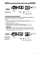
9.2 Special display
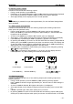
If a measured value is set as the primary display, then by pressing the
or keys the
following values can be displayed separately. These values are each displayed for approxi-
mately 3 s:
• Lowest value
• Peak value
• Switch point(s)
• Sensor 1, 2 or 3
The relevant lowest and peak values are reset by pressing the
and keys simultane-
ously during normal operation. If the reset has been successful, rES (reset) is displayed to
confirm this.
10 Output response
The HDA 5500 has a through analogue output, the signal of which is proportional to an input
signal. In addition, depending on the model and type, the HDA 5500 is available either
without switching outputs, or with two or four switching outputs.
10.1 Analogue output
On the analogue output a 4..20 mA or 0..10 V signal is available. The signal is proportional to
the input signal of one of the sensors or of the differential value. Both the allocation of the
output signal to sensor or differential value and the type of signal can be adjusted during
normal operation.
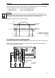
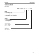
10.1.1 Analogue output set to 4..20 mA
Connection example for analogue output set to 4..20 mA:
AGND
RL
max
= 400
I
out
= 4..20 mA
Analog. Out