
User Manual
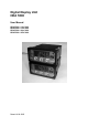

HDA 5500 User Manual
- 8 -
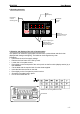
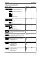
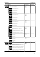
7.2 Overview of basic settings menu
Menu point Setting Setting range Default setting
Allocation of switching output 1 to sensor (S.S.1)
Switching output 1 allocated to sensor 1
Switching output 1 allocated to sensor 2
SEn.1
SEn.2
SEn.3
DiFF
SEn.1
Switching output 1 allocated to sensor 3
Switching output 1 allocated to differential value
(sensor 1 - sensor 2)
Switching function switching output 1 (S.M.1)
Switching output 1 set to switch point and
hysteresis mode
Switching output 1 set to switching window
SP
Win
SP
Switching direction switching output 1 (S.d.1)
Relay activated
Relay deactivated
on
oFF
on
Switch-on delay switching output 1 (T.on1)
Time, in seconds, which must elapse once the particular switch
point has been reached or exceeded in order for a switching
function to occur.
0..99.99 0
Switch-off delay switching output 1 (T.oF1)
Time, in seconds, which must elapse once the value has fallen
below the particular switch-back point in order for a switching
function to occur.
0..99.99 0
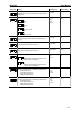
Allocation of switching output 2 to sensor (S.S.2)
Similar to switching output 1 (see above), and likewise for:
• Switching function (S.M.1)
• Switching direction (S.d.2)
• Switch-on delay (T.on.2)
• Switch-off delay (T.oF.2)
SEn.1
SEn.2
SEn.3
DiFF
SEn.1
Allocation of switching output 3 to sensor (S.S.3)
Similar to switching output 1 (see above), and likewise for:
• Switching function (S.M.3)
• Switching direction (S.d.3)
• Switch-on delay (T.on.3)
• Switch-off delay (T.oF.3)
SEn.1
SEn.2
SEn.3
DiFF
SEn.1
Allocation of switching output 4 to sensor (S.S.4)
Similar to switching output 4 (see above), and likewise for:
• Switching function (S.M.4)
• Switching direction (S.d.4)
• Switch-on delay (T.on.4)
• Switch-off delay (T.oF.4)
SEn.1
SEn.2
SEn.3
DiFF
SEn.1