
Owner manual


2
1.DISASSEMBLY
A) Relieve the fluid side pressure
completely from the accumulator.
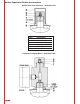
Unscrew valve protection cap
(item 6 if applicable) and valve
seal cap (item 5).
For bottom repairable bladder
accumulators with 7/8"-14 UNF
gas valve proceed to step 1.B.
For top repairable bladder,
bottom repairable bladder with
M50x1.5 gas valve, diaphragm,
and piston type accumulators
proceed to step 1.C.
B) Insure there is a minimum of 150
PSI gas precharge pressure in
the accumulator by attaching the
proper HYDAC Charging and
Gauging Unit (refer to HYDAC
Charging and Gauging Unit
brochure #02071833). If the gas
precharge pressure is too low,
increase it to 150 PSI. Once the
gas precharge pressure is set
remove the Charging and
Gauging Unit from the gas valve.
Remove and discard lock nut
(item 4) and replace it with the
new low profile lock nut (item 4)
furnished with the permanent
gauging block. Torque the new
low profile lock nut. Proceed to
step 1.C.
C) Attach the proper HYDAC
Charging and Gauging Unit and
completely relieve the gas
precharge pressure. Refer to
HYDAC Charging and Gauging
brochure #02071833.
D) After the gas precharge pressure
is completely relieved, remove
the Charging and Gauging Unit
from the gas valve.
E) Remove and discard the gas
valve core (item 3) and o-ring
(item 7) from the gas valve. Be
sure to use a gas valve core tool
to remove the gas valve core.
The use of any other implement
may damage the internal threads
of the gas valve, thus the bladder
or complete accumulator may
have to be replaced.