
Owner manual


2.ASSEMBLY
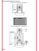
A) Before attaching the HYDAC
Permanent Gauging Block, be
certain the o-ring (11 x 2) in the base
of the block is properly seated.
For diaphragm, piston, bottom
repairable bladder with M50 gas
valve, and top repairable bladder
accumulators proceed to step 2.B.
For bottom repairable bladder
accumulator with 7/8"-14 UNF
gas valve proceed to step 2.C.
B) For top repairable bladder
accumulators, first screw on the
modified valve protection cap
(item 6A). Screw the Permanent
Gauging Block onto the
accumulator gas valve (use a 32
mm Open End Wrench), and
torque to 50 Newton Meters (37
foot pounds). Proceed to step
2.D.
C) Screw the Permanent Gauging
Block onto the accumulator gas
valve, hand tighten only. Use a
50 mm open end wrench or
equivalent (for top repairable
accumulators use a 32 mm Open
End Wrench), turn the Permanent
Gauging Block just until it is
tight. DO NOT OVER TIGHTEN. If
the Permanent Gauging Block is
over tightened at this stage of
installation the bladder may twist
in the shell and fail.
Attach appropriate HYDAC
Charging and Gauging Unit (refer
to HYDAC Charging and Gauging
Brochure #02071833). Apply dry
nitrogen gas charge of 150 PSI
to the accumulator. This will
secure the bladder and prevent it
from twisting in the shell when
tightening the Permanent
Gauging Block. Remove the
HYDAC Charging and Gauging
Unit. Torque the Permanent
Gauging Block to 50 Newton
Meters (37 foot pounds).
D) Attach appropriate HYDAC
Charging and Gauging Unit (refer
to HYDAC Charging and Gauging
Unit Brochure #02071833) and
apply proper gas precharge
pressure. Remove HYDAC
Charging and Gauging Unit.
E) Screw on the valve seal cap
(item 5), torque to 30 Newton
Meters (22 foot pounds).
3