AQUA-LAB™ Chemical Dispensing System Installation Manual REV M
Installation Manual Table of Contents Specs ....................................................................................................................................................... - 5 MD5 Panel Diagram ............................................................................................................................... - 6 Motor Starter / Pump Diagram ...............................................................................................................
Installation Manual Specifications 1. 2. 3. 4. 5. 6. 7. 8. 9. 10. Operating water pressure: 200 psi (Factory set) Pneumatic operating pressure: 100 psi (Factory set) Maximum water source temperature 140° F Operating ambient temperature: 40-120° F Electrical supply a. 208/230 or 480 volts (3-phase) b. 3 hp pump 11.5 amps @ 230 volts or 5.8 amps @ 480 volts c. Overload Setting 12.0 @ 230 volts or 6.0 @ 480 volts Operate solenoid valves with 24VAC, 24VDC, 120VAC a. 1.5 amps per port Water supply a. 1.
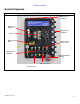
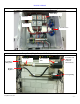
Installation Manual System Diagrams MD5 Panel Mounting Slots (2 top, 2 bottom) Primary Air Regulator Individual Air Regulators Air Valve M12 Junction Block Hydra-Cannon Water Valve Hydra-Cannon Manifold Tri-Foam Manifold (optional) Water Ports (front) Air Ports (back) © Hydra-Flex Inc 2011 -2-
Installation Manual Motor Starter (Dual Source / Dual Pump Shown) Timer Relay Contactor Overload Current Sensor Pump Stand (Single Pump with Back-up shown) Y-Strainer Feed lines to MD5 panels Thermal Relief Valve Powerfast cord (plugs into bottom of motor starter) Pressure Regulator Back-up Pump © Hydra-Flex Inc 2011 -3-
Installation Manual 5 Easy Steps for Installation Complete Pre-Installation Checklist before these steps. 1. Unpack 2. Hang the equipment 3. Make connections 4. Start-up 5.
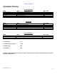
Installation Manual Estimated Timeline Pre-Installation Who Task Est. Time Distributor & Customer Plumber Electrician Technician Technician Technician Determine location to install equipment Install water supply line Install electrical supply line Label all controller relays at MCC or junction box Run solution and air lines Install air supply line 1 hr 4 hrs 4 hrs 1 hrs 5 hrs 1 hr Total Labor Hours 16 hrs Installation Who Task Est.
Installation Manual Installation Instructions General Skill Level • Mechanical: Basic - mounting equipment • Electrical: Advanced - three phase power and controls knowledge (local codes knowledge required) • Plumbing: Moderate – principal supply line required • Pneumatic: Basic- pneumatic utility connection required • Chemical Knowledge: Moderate : Advanced - chemical titrations required Tools and Equipment Needed • • • • • • Drill with Phillips head Concrete drill bit 3/8” Concrete drill bit 5/32” Hammer
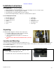
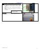
Installation Manual Pump Assembly – need to be within 6’ of furthest Aqua-Lab panel 1. Drill 3/8” holes in wall for bottom slots (20” on center pump nose down, 3.5” on center pump nose sidewise – Dual stand) 2. Insert concrete anchors, set pump on bolts and tighten down. 3.
Installation Manual Feed Water Connection **PRIOR TO CONNECTION, ENSURE THAT THE FEED LINES ARE FREE OF DEBRIS BY FLUSHING OUT THE LINES FOR 15 MINUTES • Connect pre-run main water supply line to pump inlet with hose supplied.
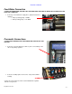
Installation Manual Electrical Connections 1. Electrical Connections a. Wire yellow homerun control cables to car wash control panel (See diagram below for wiring schematic) Manifold position below designates which port is associated to what color wire. • Example: if you want Presoak 1 to be on manifold port 2, connect the green wire to your controller relay for Presoak 1.
Installation Manual 2. Electrical Connections a. Connect yellow homerun control cables to car wash control panel (See diagram below for wiring schematic) Manifold Position below designates which port is associated to what color wire. • Example: If you want Presoak 1 to be on manifold port 2, then connect the green wire to your controller relay for Presoak 1.
Installation Manual Startup Pump Priming Instructions 1. Pull each pump outlet line at AQUA-LAB manifold quick-connect. Open ball valve until a steady stream of water is flowing, and then reconnect. 2. Start the pumps one at a time using the motor starter. Ensure that pump rotation is correct as indicated on pump and that 200 psi can be reached. o Remove pump motor cover and look at shaft to confirm correct rotation (clockwise) 3.
Installation Manual Appendix Layout Drawing © Hydra-Flex Inc 2011 - 12 -