Operating Manual AQUA-LAB™ Chemical Dispensing System Operating Manual REV M © Hydra-Flex Inc 2011 -1-
Operating Manual Table of Contents Specifications .......................................................................................................................................... - 3 Illustrations ......................................................................................................................................... - 4, 5 Initial Injector Setup ...............................................................................................................................
Operating Manual Specifications 1. 2. 3. 4. 5. 6. 7. 8. 9. 10. Operating water pressure: 200 psi (Factory set) Pneumatics operating pressure: 100 psi (Factory set) Maximum water source temperature 140° F Operating ambient temperature: 40-120° F Electrical supply a. 208/230 or 480 volts (3-phase) b. 3 hp pump 11.5 amps @ 230 volts or 5.8 amps @ 480 volts c. Overload Setting 12.0 @ 230 volts or 6.0 @ 480 volts Operate solenoid valves with 24VAC, 24VDC, 120VAC a. 1.5 amp per port Water supply a. 1.
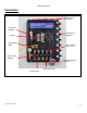
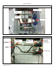
Operating Manual Illustration MD5 Panel Mounting Slots (2 top, 2 bottom) Primary Air Regulator Individual Air Regulators Air Valve M12 Junction Block Hydra-Cannon Water Valve Hydra-Cannon Manifold Tri-Foam Manifold (optional) Water Ports (front) Air Ports (back) © Hydra-Flex Inc 2011 -4-
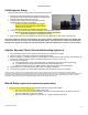
Operating Manual Motor Starter (Dual Source / Dual Pump Shown) Timer Relay Contactor Overload Current Sensor Pump Stand (Single Pump with Back-up shown) Y-Strainer Feed lines to MD5 panels Thermal Relief Valve Powerfast cord (plugs into bottom of motor starter) Pressure Regulator Back-up Pump © Hydra-Flex Inc 2011 -5-
Operating Manual Initial Injector Setup (Based on field experience this is HFI’s recommended staring point) 1. Using the recommended starting point (appendix page 10) or the target flow rate and the chemical dilutions chart (appendix) install the appropriate injector into each port 2. Connect pre-run solution lines to each Injector with the supplied coupler and push connect fitting a.
Operating Manual Triple Foam Setup (for MD5 if ordered with extra regulators) If your MD5 panel was ordered with 3 air valves and 5 air regulators or with 5 air valves and 7 air regulators the below instructions will show you how to setup your triple foam.
Operating Manual Optimizing the System Consistently achieve the desired cleaning and presentation/performance using the least amount of chemical and water Injectors vs. Metering Tips vs. Nozzles The key to optimizing the system is through trial and error. Don’t be afraid to try these steps to achieve your ideal performance.
Operating Manual Chemical Usage Measuring Verify titration of chemicals before proceeding 1. Setup lab scale with small bucket of chemical to be measured. 2. Put the suction line into the bucket. 3. Run the application being tested to “prime” the line. (All air bubbles must be removed for accuracy) 4. Record the Initial Weight from the scale. (Tarring the scale with weight on the scale can affect accuracy) 5. Run the application for 6 vehicles (or manually for the same it would be on for 6 vehicles). 6.
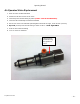
Operating Manual Air Operated Valve Replacement 1. Shut off valve to MD5 manifold 2. Disconnect air line from front of valve 3. Unscrew quick connect fitting by hand (DON’T LOSE BLACK WASHER) 4. Unscrew valve assembly from black manifold 5. Screw new valve into manifold (hand tighten should be enough, if not wrench 1/8 turn) 6. By hand, screw quick connect fitting to front of valve – Hand Tight ONLY 7. Push air line back into fitting 8.
Operating Manual Troubleshooting Pump Issues Problem Potential Causes Solutions Pump Operates, but only delivering 100150 psi Incorrect Motor Rotation Reverse rotation by interchanging two leads Pump not Primed Missing 1 of 3 phases Inadequate water supply See Priming Instructions Wire according to diagram Check pressure on inlet side of pump to be sure positive pressure is maintained Replace with larger piping Make sure connections are tight Replace worn parts or entire pump, clean parts if require
Operating Manual Clogged injector nozzle Defective Injector Product Specific – Sonny’s Rain Bar Manifold Inlet Clogged (rare) Valve malfunction, valve not opening No Flow from injector Injector Stainless Steel disintegrating from HF Clogged injector No water supply Strong Hydro-Fluoric Acid Remove injector and blow out any debris with compressed air Replace injector Remove elbow at inlet to foam generator and remove nozzle Remove end fittings and retention rod. Clean out inlet holes to allow full flow.
Operating Manual Valve Issues Problem Valve won’t open Potential Causes Solutions Air pressure too low Ensure primary air regulator reading at least 60 psi, turn up to 80-90psi if possible and check again Remove valve from manifold, Carefully remove top of valve (caution – under high spring pressure) push white piston up with small allen wrench from opposite end and check o-ring condition. Replace and lubricate if needed.
Operating Manual Appendix © Hydra-Flex Inc 2011 - 14 -
Operating Manual © Hydra-Flex Inc 2011 - 15 -
Operating Manual Setup Starting Point Recommended Aqua-Lab Setup Starting Point Chemical Application Injector Range Air Nozzles Presoak 618057 618086 20 - 30 KSS12 X4 CTA 618040 618070 35 - 55 1080 X4 Wrap 618057 618070 10 - 20 App. Dep. Mitter 618057 618070 10 - 20 App. Dep. TriFoam Colors 618057 618070 10 - 20 App. Dep. Bug Blaster 618040 618057 App. Dep. App. Dep. Under Carriage 618051 618070 App. Dep. App. Dep.
Operating Manual Chem-Flex Injector Listing Aqua-Lab Chem Flex Injector Listing Part Number 618029 618040 © Hydra-Flex Inc 2011 # Barbs 1 1 GPM 0.25 0.50 618051 618057 618070 618083 618086 618098 618125 629029 1 1 1 1 1 1 1 2 0.75 1.00 1.50 2.00 2.30 3.20 5.40 0.25 629040 629051 629057 629070 629083 629086 629098 629125 2 2 2 2 2 2 2 2 0.50 0.75 1.00 1.50 2.00 2.30 3.20 5.
Operating Manual AQUA-LAB WARRANTY Factory Limited Hydra-Flex Inc warrants its equipment to be free from defect in material or workmanship under proper normal proper use for a period of one (1) year beginning the date of purchase. The Hydra-Flex Inc’s liability shall be limited to repair or replacement of parts found to be defective within the warranty period and following Hydra-Flex Inc’s inspection.