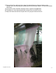
Tsunami™ Dispensing Arch Using AQUA-LAB™ Chemical Dispensing System REV A © Hydra-Flex Inc 2011 -1-
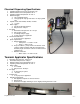
Chemical Dispensing Specifications 1. 2. 3. 4. 5. 6. 7. 8. 9. Operating water pressure: 200 psi (Factory set) Maximum water source temperature 140° F Operating ambient temperature: 40-120° F Electrical supply a. 120 / 208 Single Phase b. 1.5 hp pump 20 amps @ 120 volts or 10 amps @ 208 volts Operate valves with 24VAC, 24VDC, 120VAC a. < .5 amp Water supply a. 3/4” ID flooded inlet required b. Inlet pressure: 2-60 psi Air supply a. Pneumatics inlet pressure: 60 - 100 psi b. 3/8” feed per system c.
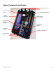
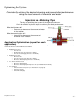
System Component Identification Air Regulator 1, 2, 3 Air Solenoid Valve Air Inlet (3/8” Poly) Board Mounting Slots Pneumatically Actuated Valve Water Feed From Pump (200psi) Triple Foam Manifold Chemical Injector 3x Outlet to Applicator Air Outlet 1, 2, 3 © Hydra-Flex Inc 2011 -3-
1. Mount pump using 4x 3/8” wedge Anchors provided (3/8” hammer drill required) a. Mounting slots 3.75”W x 3.38”H 2. Mount electrical box and delivery panel using Tapcon anchors provided (5/32” hammer drill required) a. Electrical Box – Hole spacing 7.4”W x 3.5”H b. Panel – Slot spacing 17.5”W x 15”H 3. Run ¾” water line to the inlet of the pump 4. Close the ball valve on the pump outlet line and open the feed to the pump 5.
18. Run chemical lines with foot valves from the chemical barrels to the hose barbs on the injectors and install metering tips according to desired chemical dilution ( see chemical dilution ratio chart) 19. Using the car wash controller manually fire the signal for the application. 20. The pump, air valve and pneumatically actuated valve should all turn on. 21. Adjust the chemical ratio and air pressure until you get the desired results.
Optimizing the System Consistently achieve the desired cleaning and presentation/performance using the least amount of chemical and water Injectors vs. Metering Tips The key to optimizing the system is through trial and error. Don’t be afraid to try these steps to achieve your ideal performance.
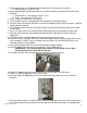
Chemical Usage Measuring Verify titration of chemicals before proceeding 1. Setup lab scale with small bucket of chemical to be measured. 2. Put the suction line into the bucket. 3. Run the application being tested to “prime” the line. (All air bubbles must be removed for accuracy) 4. Record the Initial Weight from the scale. (Tarring the scale with weight on the scale can affect accuracy) 5. Run the application for 6 vehicles (or manually for the same it would be on for 6 vehicles). 6.
Troubleshooting Injector Vacuum Check (for troubleshooting injectors) 1. At the ChemFlex injector, remove the chemical feed line from the injector hose barb. 2. Attach the tubing of the vacuum gauge to the ChemFlex hose barb 3. With the pump(s) on, manually activate the chemical that is to be tested at the main car wash control cabinet. An injector that is working properly will have a reading greater than or equal to (≥) 20 in Hg 4.
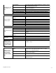
Inlet Restriction Pump Operates, but delivers little or no water Pump won't start or run at full speed Inadequate water supply Undersized piping Leak on the Inlet side Worn or defective pump parts Blown fuse or circuit breaker Defective Motor Starter contactor Incorrect Motor Voltage Defective motor Pump components damaged Check all in-line filters and inlet plumbing for restrictions.
PROBLEM System won't regulate up to 200 psi Flow at arch is too low POTENTIAL CAUSES Follow priming instructions Remove regulator and clean out debris Replace check valve if broken Replace Regulator Replace Pump Incorrect Injector Flow Rate Selection System pressure too low Foam Generator Plugged Downstream pluming restrictive Replace with desired injector size Valve malfunction Ensure valve is receiving at least 60 psi Valve may be assembled incorrectly Disassemble valve and clean out debris (See va
Appendix © Hydra-Flex Inc 2011 - 11 -
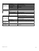
Chem-Flex Injector Listing Aqua-Lab Chem Flex Injector Listing # Part Number Barbs GPM 618029 1 0.25 618040 1 0.50 © Hydra-Flex Inc 2011 618051 618057 618070 618083 618086 618098 618125 629029 1 1 1 1 1 1 1 2 0.75 1.00 1.50 2.00 2.30 3.20 5.40 0.25 629040 629051 629057 629070 629083 629086 629098 629125 2 2 2 2 2 2 2 2 0.50 0.75 1.00 1.50 2.00 2.30 3.20 5.
AQUA-LAB WARRANTY Factory Limited Hydra-Flex Inc warrants its equipment to be free from defect in material or workmanship under proper normal proper use for a period of one (1) year beginning the date of purchase. The Hydra-Flex Inc’s liability shall be limited to repair or replacement of parts found to be defective within the warranty period and following Hydra-Flex Inc’s inspection. Hydra-Flex Inc shall have the option requiring the return of defective material to establish the purchaser’s claim.