
Installation Sheet


– 4 –
For installations that are any combination of decks, walls, and pony walls, use the same methods to determine
critical heights. Remember that all supports must be at the same height and must establish a plane that is level
front to back and side to side.
5. HOT WATER HEATER: As a rule of thumb, the capacity of the hot water heater needs to be 2/3 of the capacity
of the bathtub.
ELECTRICAL REQUIREMENTS:
Whirlpool Only: 115V 15Amp Dedicated GFCI Protected
Thermal Air: 115V 15Amp Dedicated GFCI Protected
A dedicated 15AMP GFCI Breaker of Protected outlet(s) for each load item i.e. pump, blower, heater, ect.
WARNING: When using electrical products, basic percautions should always be followed.
DANGER: RISK OF ELECTRICAL SHOCK. Connect only to a circuit protected by a ground fault circuit interrupter.
Grounding is requirred. All electrical connections should be made by a licensed electrician. Installation of
Hydro Systems bathtubs must meet all a[pplicable codes and regulations.
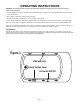
INSTALLING THE TUB
1. The installation of the tub/whirlpool tub must meet all applicable regulations and codes. Access must be provided
for future service or removal of the equipment without removing the tub or damaging the building structure or nish.
An access panel at least 14” high by 16” wide must be located directly in front of the equipment. The optional Hydro
Systems skirt with removable panel will satisfy this requirement. Minimum
clearance in front of any panel should be 30”
2. TEST THE WHIRLPOOL or THERMAL AIR SYSTEM BEFORE YOU INSTALL THE TUB. All Hydro Systems
whirlpool / thermal air tubs are fully tested at the factory before shipping. However, it is the responsibility of the install-
er to check the system before installing the tub; if the tub is to be set in “rough framing” and can be accessed from all
sides after setting, skip to paragraph 4 below. If the tub will be set in “nished framing” and can’t be accessed from all
sides, you must test the tub outdoors before setting it. Here’s how:
•
Put the tub on a at surface such as a driveway or lawn.
•
Tape over the drain.
•
Fill the tub with a garden hose. Fill it to at least 1” above the highest jet.
•
Plug the pump into a 110v GFCI protected outlet.
•
Start the pump / blower by pressing the Air Switch button.
•
Check the entire system for leaks. Some components will be inaccessible after the tub is installed,
A
1"
X
Figure 2a
B
X
Figure 2b
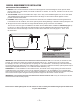
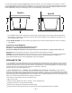
On tubs with integral tile anges, (Figure 2a) measure the distance from the underside of the tub deck to the bot-
tom of the tub base at the drain end of the tub (A) plus 1" for the mortar bed. On tubs with integral tile anges and a skirt
panel, (Figure 2b) measure the distance from the top of the stringer to the oor (X) must equal the distance from the
bottom of the skirt to the top of the deck (B), minus 1/4" (the thickness of the tub deck)