
Installation Sheet
– 5 –
so check each component and each connection all around the tub.
•
If the tub has optional equipment, now is the time to check those components, too.
If the tub has an in-line heater, plug it into a separate 110v GFCI protected source while the pump is running.
(The heater will operate only when the pump is running). The heater’s indicator light will be on when the heater
is operating.
DO NOT INSTALL THE TUB if the system is leaking. Contact your dealer or call Hydro Systems at 661-775-0686.
If the whirlpool system is performing properly and there are no leaks in the system, you are now ready to set the tub.
NOTE: Bathtub serial number will be needed in the event that “any” type of service is required.
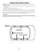
3. SETTING THE TUB
•
Install the waste & overow on the tub.
•
Your tub has the standard single speed pump or varible speed or blower, remove the hold-down bolts or screws
securing the components to the platform prior to setting the tub.
•
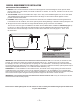
The tub must be supported evenly around the perimeter of the deck and also under the entire bottom.
•
To set the tub, mix a stiff batch of mortar (without gravel) and pile more than enough on the oor.
It may be necessary to construct a dam to contain the mortar. Do not use drywall compound, plaster of Paris or
foam - doing so will void the warranty.
•
Lower the tub into position. Slip the drain into the waste line as it goes down. Allow the tub to settle into the wet
mortar, squishing the excess out at the sides and ends of the tub.
•
When the deck hits the support stringers make sure the tub is level end to end and side to side.
•
If the mortar is very deep, the tub may try to “Float” in the mortar bed. Put four to six inches of water in the tub to
hold it down. Allow the mortar to cure overnight before draining the tub.
•
Fasten the tile anges to the wall studs with galvanized nails or screws - pre-drill the holes for them rst. Note – the
tile anges are not structural and must not bear any weight. The tub must be supported from the bottom.
•
If the tub was ordered with the pump in a remote location, the pump is mounted to the platform opposite the drain.
All PVC pipe and ttings required to connect the pump to the whirlpool system are strapped to the tub. Remove
them now. The pipes are color coded , connect piping to corresponding colors. Construct a support stand for the
pump. The slope of the pipe from the suction tting up to the pump should be a minimum of 1/8” per foot. The
discharge line from the top of the pump to the tub must slope evenly up to the system. It must not go below the
pump intake or above the jet closest to the pump. The pump must not hang on the pipes. It must sit on the rubber
feet and it is not required to be bolted down. Connect both pipes to the whirlpool system and thread the unions
onto the pump. Be sure the “O” rings are in the unions. Hand tighten only, and do not use any type of joint sealant.
The use of any sealant voids the warranty.
•
There is a red tube connected to the air switch button located on the tub that connects to the top of the pump or to
the blower controler.
ELECTRICAL CONNECTION:
If the pump and/or blower is in the standard location, make sure the bolts have been removed that hold the pump or
blower to the pump platform and plug pigtail into the home’s dedicated GFCI.
FINAL CLEANUP
DO NOT USE ABRASIVE CLEANERS TO CLEAN THE BATHTUB. They may scratch or mar the surface. Liquid
soap
or a cleaner intended for berglass bathtubs should be used. Please refer to the USER CARE AND MAINTENANCE
section. Do not use wire brushes or metal tools or scrappers to remove paints drips, plaster, tar, etc. If a scraping device
is required, a wood edge may be used carefully. Use lighter uid to remove any adhesive left from stickers and labels.