OWNER’S GUIDE 104 Series ADVANCED MULTI STAGE WATER TREATMENT SYSTEM 104 SERIES
INTRODUCTION THIS GUIDE IS APPLICABLE TO ALL 104 SERIES MODELS TABLE 1 SYSTEM CONFIGURATION Filtration Unit Flow Monitor Faucet Smartap 104 Series 4 Vessel Unitary Manifold Non-NSF* ® 10403002-## ® Push Button Smartap 10403001-## None 10401000-## * Note: ## - refers to specific branding of the 104 Series product.
INTRODUCTION CONDITIONS FOR USE OPTIONS AND ACCESSORIES Source Water Supply Profile Metal Or Polymer Faucet Community/Private Chlorinated/Non-Chlorinated Product water faucets are available in Chrome-Plated Brass, (EPA 1 and California Proposition 65 Compliant), Feed Water Pressure 173-690 kPa (25-100 psig) Polished Stainless Steel, or a Chrome-Plated molded Polymer Temperature 4°-38° C (40°-100° F) with black accents. Units are available with or without Light Bar. 1.
INSTALLATION REQUIREMENTS READ THIS ENTIRE INSTALLATION AND SERVICE GUIDE BEFORE BEGINNING INSTALLATION This 104 Series Advanced Multi-Stage Water Treatment System is designed for ease of installation and serviceability. It is constructed with the finest materials available. Using these instructions and paying close attention to parameters outlined within "CONDITIONS FOR USE" detailed on Page II will ensure a successful installation.
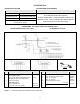
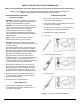
INTER-COMPONENT CONNECTIONS Connections between the cold water supply line, filtration unit, product water faucet, and optional accessories are accomplished using plastic tubing and push-together quick-connect type fittings. PLASTIC TUBING QUICK-CONNECT FITTINGS 1. Cut tube ends square and straight. Do not deform the tube (i.e., cause tube to compress its diameter so it is no longer round). Fittings consist of two parts: a Body and a colored Collet.
SADDLE-TAPPING VALVE INSTALLATION ON COPPER TUBE CAUTION: This saddle-tapping valve is not designed for installation on flex line tubing. NOTE: State and local plumbing codes may prohibit use of saddle-tapping valves. 1. 4. Connect source water feed tubing to valve body using compression fitting. CAUTION: If no shut off valve is installed under sink, close main water valve during this Installation. a. Slide nut and sleeve onto tubing (in that order). Locate shut off valves on water lines under sink.
INLET ADAPTER VALVE INSTALLATION NOTE: This assembly is offered as an optional installation method. Make sure it is approved for use under State and local plumbing codes before ordering kit (P/N 42500004). NOTE: Use this assembly on U.S.N.P.T.* pipe thread fittings only. 1. 5. Replace existing rubber grommet on cold water supply line with grommet supplied in kit (Item 3). CAUTION: If no shut off valve is installed under sink, close main water valve during this installation.
PRODUCT WATER FAUCET SITE PREPARATION Refer to Faucet Installation Instructions (Pages 5 & 7) for site location and mounting hole specifications. Primary considerations for site selection are convenience of use and an open area under sink. Always check underside of selected location for obstructions. STAINLESS STEEL SINK PORCELAIN/ENAMEL OVER STEEL OR CAST IRON SINKS 1. 1. Use a center punch to make a small indentation to mark center of desired location.
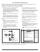
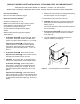
PRODUCT WATER FAUCET INSTALLATION - STAINLESS STEEL OR CHROME FAUCET Install faucet on flat surface at least 2" in diameter. Unused 1 1/4" hole is ideal. Steps unique to a specific configuration are so noted. All other steps are common to either configuration. 4. Install faucet connector (Item 4, packaged with faucet) onto faucet nipple. Do not over tighten. New Faucet Installation Refer to Faucet Site Preparation, Page 4. 5. Install 3/8” blue tube into faucet connector.
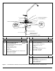
12 1 8 (PUSHBUTTON SMARTAP ) ® 9 (FAUCET SMARTAP ) 2 ® 10 SINK OR COUNTER MATERIAL 11 MONITOR CONNECTOR 7A (PUSH BUTTON SMARTAP) 3 5 (FAUCET SMARTAP ) 6 7 (FAUCET SMARTAP ) FAUCET NIPPLE 4 DRINKING WATER LINE FROM POST-FILTER TO FAUCET(3/8" BLUE TUBING) A Chrome Plated Metal Faucet Item A A 1 2 4 5 6 7A Description B+C Part No.
PRODUCT WATER FAUCET INSTALLATION - POLYMER FAUCET Install on flat surface at least 2 7/16" in diameter. Unused 1 1/4"- 1 7/16" opening is ideal. New Faucet Installation NOTE: Faucet is packaged for right-hand operation. For left-hand operation, realign handle by completing Step 5. Refer to Faucet Site Preparation, Page 4. NOTE: Item callouts in Step 5 refer to Page 8, Figure 9. Replacement Faucet Installation Verify size of existing hole.
Item Description Part No. Item Description 1 Cover, Knob - Chrome - Plated 35800502 6 “O” ring, Spout 2 Screw, Knob 32701021 7 Body Assembly - Chrome Plated Plain 3 Knob, Faucet - Black 20800904 4 Spout, Faucet Polished 35801308 5 Tip, Spout - Black 20801504 Figure 9 Body Assembly - Chrome Plated 3 LED Part No.
Item ® Faucet Smartap Monitor Module Cover and Flow Switch Assembly Description Part No. 1 Cover, 4-vessel Manifold - No Monitor 43014055 2 Bracket, Mounting 21100001 3 Screw, Mounting Bracket 32701006 4 Screw, Retaining Plate 32701038 5 Cover Assy, Inlet Valve w/”O” Rings 42200002 6 “O” Ring, Inlet Valve Cover 34201024 7 Elbow, 1/4" Stem w/white collet 33503502 8 Elbow, 3/8" Stem w/blue collet 33503503 9 Control Assembly, Flow 0.
ACTIVATING THE SYSTEM CAUTION: Make sure all water supply lines, drain lines, and fittings are secure and free from leakage. 5. 1. Open saddle-tapping valve. Check for leakage. CAUTION: Verify battery connector alignment before making connection (Figure 11). 2. Open product water faucet and let water flow to drain for at least 10 minutes. This will expel the air from the system. Connect battery (Item 24) by pressing clip onto battery terminals. 6. Replace module cover and tighten screws. 3.
ROUTINE MAINTENANCE RECOMMENDATIONS HAVE ALL COMPONENTS ON HAND AND READY BEFORE BEGINNING PROCEDURE. A CLEAN WORK AREA AND EQUIPMENT ARE ESSENTIAL TO PROPERLY CLEAN AND/OR SANITIZE THE SYSTEM. (I.e., CLEAN HANDS, TOOLS, WORK SURFACE, AND CONTAINERS) SERVICE REQUIREMENTS To insure the system operates at its optimum level, certain routine maintenance must be performed. Frequency of maintenance performance will depend on feed water quality and level of system usage.
CLEANING, SANITIZING, AND CARTRIDGE REPLACEMENT 9. NO WATER FLOW MONITOR: Complete Steps 26 - 29 CAUTION: Excessive concentrations of bleach will damage plastic and rubber components. Rinse all parts that contact bleach thoroughly with clean potable water. ® OPTIONAL SMARTAP WATER FLOW MONITOR: Complete Steps 18 – 29 Mix sanitizing solution of 1.5 ml (1/3 teaspoon) of household bleach and 3.8 L (1 gallon) of clean, potable water in the bucket. Mix the solution well.
CLEANING, SANITIZING, AND CARTRIDGE REPLACEMENT 30. System is ready to use. Should there be any aftertaste or odor to the water or ice cubes, repeat Step 29. 27. Open product water (and extra point-of-use) faucet. Let water flow until all air has been expelled from system. 28. Close product water (and extra point-of-use) faucet. In 5 minutes, check the connections for leaks and correct if necessary. Icemaker: Let the tray/bin fill with ice cubes. Discard all ice cubes to the drain.
INSTALLATION AND SERVICE RECORD DATE INSTALLED SYSTEM: SERVICE FLOW 0.
INSTALLATION AND SERVICE RECORD DATE INSTALLED SYSTEM: SERVICE FLOW 0.
LIMITED WARRANTY Subject to the conditions and limitations described below, WaterGroup warrants its Model 104 Series Advanced MultiStage Water Treatment Systems (excluding cartridge filters and battery), when installed in accordance with our specifications, to be free from defects in materials and workmanship under normal use within the operating ® specifications for a periods of two (2) years from the date of purchase.