
Owner's manual


- 5 -
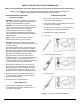
PRODUCT WATER FAUCET INSTALLATION - STAINLESS STEEL OR CHROME FAUCET
Install faucet on flat surface at least 2" in diameter. Unused 1 1/4" hole is ideal.
Steps unique to a specific configuration are so noted. All other steps are common to either configuration.
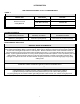
New Faucet Installation
Refer to Faucet Site Preparation, Page 4.
Replacement Faucet Installation
Verify size of existing hole is 1 1/4".
NOTE: Item callouts refer to Page 6, Figure 7 unless
noted otherwise. Part numbers for each callout
are specified according to faucet type:
Chrome-Plated Faucets (brass faucet nipple):
Table A.
Stainless Steel Faucets (copper faucet nipple):
Tables B and C.
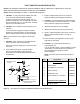
1. Push Button Smartap
: Verify faucet body, rubber
body washer, metal base washer, and rubber base
washer are in place above sink (Items 1, 12, 2 and 8).
Optional Faucet Smartap
: Verify faucet body,
rubber body washer, metal base washer, light bar
base washer, light bar assembly, and washboard
gasket are in place above sink (Items 1, 12, 2, 9, 10,
and 11).
2. Push Button Smartap
: Place faucet over hole.
Optional Faucet Smartap
: Insert monitor cord into
mounting hole and place faucet over hole.
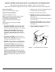
3. CAUTION: Do not pinch, kink, or otherwise deform
monitor cord. Align cord with cutout in plastic spacer.
Push Button Smartap
: Install locating washer,
faucet washer, and nut on faucet nipple below sink
and snug them up (Items 7A, 6, and 5). Be sure to
align faucet properly before tightening. Do not over
tighten.
Optional Faucet Smartap
: Install slotted washer,
spacer, faucet washer, and nut on faucet nipple below
sink and snug them up (Items 7, 3, 6, and 5). Be sure
to align faucet properly before tightening. Do not over
tighten.
4. Install faucet connector (Item 4, packaged with faucet)
onto faucet nipple. Do not over tighten.
5. Install 3/8” blue tube into faucet connector.
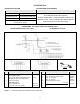
6. CAUTION: Blue 3/8" tube connecting module to the
faucet must run with no sharp bends or loops (See
Page II, Figure 1).
Connect 3/8" blue tube to 3/8" swivel elbow located on
the rear of module.
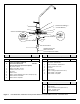
7. Optional Faucet Smartap
: Connect monitor cord
to telephone-style connector located on manifold
cover (Figure 6).
8. The basic installation is complete and system is
ready for activation (see Page 10).
FROM
SMARTAP SERVICE
INDICATOR LIGHT
Figure 6 Connecting Monitor cord to Manifold.