
Owner's manual


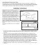

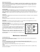

Bridging (Figure 6)
Humidity or the wrong type of salt may create a cavity between the water and the salt.
This action, known as “bridging”, prevents the brine solution from being made, leading to
your water supply being hard.
If you suspect salt bridging, carefully pound on the outside of the plastic brine tank or
pour some warm water over the salt to break up the bridge. This should always be
followed up by allowing the unit to use up any remaining salt and then thoroughly
cleaning out the brine tank. Allow four hours to produce a brine solution, then manually
regenerate the softener.
Care of Your Softener
To retain the attractive appearance of your new water softener, clean occasionally with a
mild soap solution. Do not use abrasive cleaners, ammonia or solvents. Never subject
your softener to freezing or to temperatures above 110
°F (43°C).
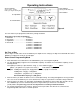
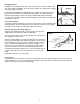
Cleaning the Injector Assembly (Figure 7)
Sediment, salt and silt will restrict or clog the injector. A clean water
supply and pure salt will prevent this from happening.
The injector assembly is located on the right side of the control valve.
This assembly is easy to clean.
Shut off the water supply to your softener and reduce the pressure by
opening a cold soft water faucet. Using a screwdriver, remove the two
screws holding the injector cover to the control valve body. Carefully
remove the assembly and disassemble as shown in Figure 7. The
injector orifice is removed from the valve body by carefully turning it
out with a screwdriver. Remove the injector throat the same way.
Carefully flush all parts including the screen. Use a mild acid such as
vinegar or Pro-Rust Out to clean the small holes in the orifice and
throat.
Reassemble using the reverse procedure.
Resin Cleaner
An approved resin cleaner MUST be used on a regular basis if your water supply contains iron. The amount of resin
cleaner and frequency of use is determined by the quantity of iron in your water (consult your local representative or
follow the directions on the resin cleaner package).
8
INJECTOR BODY
INJECTOR THROAT
INJECTOR NOZZLE
“O” RING
INJECTOR COVER
INJECTOR SCREEN
SCREW
Figure 7
Bridging
Figure 6