
Owner's manual


4
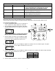
1. Place the iron filter and the chemical feeder container on a flat surface in desired location, near a drain and 120 volt AC
outlet. Subjecting your filter to freezing or to water temperatures above 110°F (43°C) will void the warranty.
NOTE: Some units are shipped with the media bed in separate bags. To install, unscrew the control valve from the top of
the fiberglass tank, position the riser tube in the center of the tank plugging the tube with a cloth and pour the media into
the tank in the following order: coarse, fine gravel and then the filter media. Remove the cloth and carefully screw the
valve into the tank (When replacing the media, the tank must first be inverted and the old media bed removed. See
instructions provided with the replacement media).
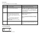
Rural Well Supply - Iron & Hardness Removal
2. Attach the installation kit or bypass to the control valve. Make the inlet and outlet connections to meet applicable
plumbing codes. A 3/4” inlet line is recommended. When sweat fittings are used, solder the adapters for the inlet and
outlet to a short length of copper pipe first. This procedure is necessary because the controls MUST NOT be subjected
to temperatures above 160°F (71°C). Then, using Teflon tape, screw the adapters for the inlet, outlet and drain into the
valve.
CAUTION: Do not use pipe thread compound as it may attack the material in the valve body.
3. On the drain, use the 1/2" hose barb supplied and a full 1/2" ID hose (not supplied) for the drain line and make the
shortest run to a suitable drain. The drain lines must be secured in position at the ends which discharges into the drain
so it cannot be inadvertently moved from the drain, resulting in chemical spillage.
4. Connect the feeder container to the control valve with the flexible polyethylene tubing provided. The connection to the
container is made with the fitting nut provided (do not overtighten).
5. Attach the 5/8” hose (supplied) to the over flow fitting on the feeder and run the hose to the floor drain.
6. Make sure the bypass valve is in the service position.
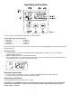
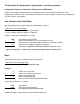
7. Plug the 24-volt transformer into a 120 VAC 60 Hz outlet. This valve has four positions: 1) Backwash 2) Brine/Rinse
3) Rapid Rinse and 4) Brine Refill. When the valve is in the Service position, the extra cycle button (far left button as
shown on Figure 4) must be pressed and held for 5 seconds before it activates. Press and hold the extra cycle button for
5 seconds to advance the valve to the “1” Backwash position. Slowly turn on the water supply and allow the unit to
backwash until the air purges out of the tank and clears the system.
8. Advance to the brine refill position “4”. Allow to fill for 5 minutes. Make sure there are no leaks in the top connection to
the feeder container.
9. Advance to the Brine/Rinse position “2”. Proper draw is indicated by upward motion of water droplets in the tube
connected to the feeder container. Allow to draw for 5 minutes to pull the air out of the feeder container.
10. Put control into the service position.
11. Set the time of day and gallons between regeneration following the information on Pages 5-8.
12. Make sure any bypass is in the service position.
13. Cautiously pour the Potassium Permanganate into the feeder and replace the cover and safety screws. (See the refilling
instructions on page 10).
14. Manually initiate regeneration after about one hour for the potassium permanganate to activate the manganese
greensand.
ALL STATE AND LOCAL GOVERNMENT CODES GOVERNING INSTALLATIONS OF THESE DEVICES MUST BE OBSERVED.