9100SXT Valve Meter Initiated Water Softener Operation Manual WQA Tested and Certified against CSA B483.1 Read all instructions carefully before operation.
ii
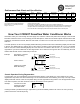
WQA Tested and Certified against CSA B483.1 Performance Data Sheet and Specification Item Number Model Number 7634 7627 7628 7629 9100SXT-20 TMI 9100SXT-30 TMI 9100SXT-45 TMI 9100SXT-60 TMI Capacity - Grains @ 15 lbs Factory @ @ 6 lbs /cu.ft 10 lbs/cu.ft /cu.
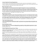
Control Operation During Programming The control will only enter the Program Mode with the valve in Service. While in the Program Mode, the control will continue to operate normally, monitoring water usage and keeping all displays up to date. Control programming is stored in memory permanently, eliminating the need for battery back-up power. Meter Immediate Control A meter immediate control measures water usage and regenerates the system as soon as the calculated system capacity is depleted.
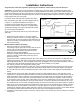
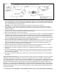
Installation Instructions All government codes and regulations governing the installation of these devices must be observed. CAUTION: If the ground from the electrical panel or breaker box to the water meter or underground copper pipe is tied to the copper water lines and these lines are cut during installation of the Noryl bypass valve and/or poly pipe, an approved grounding strap must be used between the two lines that have been cut in order to maintain continuity.
Figure 3 4. Attach the bypass valve to the control valve. Connect the inlet and outlet of the water softener to the plumbing in the house. The control valve must not be submitted to temperatures above 43°C (110°F). When sweat fittings are used, to avoid damaging the control valve, solder the threaded copper adapters to the copper pipe and then, using Teflon tape, screw the assembly into the bypass valve. CAUTION - do not use pipe thread compound as it may attack the material in the valve body. 5.
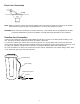
Drain Line Connection NOTE: W aste connections or drain outlet shall be designed and constructed to provide for connection to the sanitary waste system through an air-gap of 2 pipe diameters or 1 inch (22 mm) whichever is larger. WARNING: N ever insert drain line directly into a drain, sewer line, or trap. Always allow an air gap between the drain line and the wastewater to prevent the possibility of sewage being back-siphoned into the conditioner.
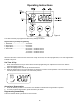
Operating Instructions Figure 4 The valve has been pre-programmed with factory settings as follows: Regeneration Cycle Step Programming 1. Backwash......................................10 minutes 2. Brine Rinse....................................60 minutes 3. Rapid Rinse...................................10 minutes 4. Brine Refill.....................................
User Programming Mode Options Abbreviation Parameter Description DO Day Override The timer’s day override setting This is an option only. Please do not adjust before consulting an authorized dealer. H Feed Water Hardness The hardness of the inlet water - used to calculate system capacity for metered systems RC Reserve Capacity CD Current Day The fixed reserve capacity The current day of week NOTES: Some items may not be shown depending on timer configuration.
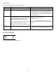
Error Codes Note: Error codes appear on the In Service display Error Code Probable Cause Recover and Resetting [Err 0] Drive motor is stalled Unplug the unit from the power source [Err 1] Drive motor is running continuously When power is restored to the unit, the Err _ display code clears. If the condition causing the error has not been resolved the Err _ code reappears in the four digit display. Do not attempt to troubleshoot this problem any further.
Manual Regeneration Cycle If you run out of softened water because of inadequate regeneration frequency, inadequate reserve capacity, power failure or unusually high water usage, you can initiate a manual regeneration simply by pressing the extra cycle button. The softener will now automatically complete a regeneration cycle and return to service. If possible, avoid water use during the regeneration cycle.
Maintenance Instructions Checking the Salt Level Check the salt level monthly. Remove the lid from the cabinet or brine tank, make sure salt level is always above the brine level (you should not be able to see water). Adding Salt Use only clean salt labeled for water conditioner use, such as crystal, pellet, nugget, button or solar. The use of rock salt is discouraged because it contains insoluble silt and sand which build up in the brine tank and can cause problems with the system’s operation.
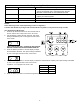
Parts Breakdown Outlet Inlet Front View Side View Top View BRINE TANK 2 Back View BRINE TANK 4 3 6 1 7 Resin 5 Model # Brine Tank (1) Valve (2) Tank (3) Distributor (4) Brine Grid (5) Resin #21501 9100SXT-20TMI 100367 91001-05 100036 (2) 19478 (2) 19725 1.5 CF 9100SXT-30TMI 100367 91001-05 100037 (2) 19478 (2) 19725 2.0 CF 9100SXT-45TMI 100367 91001-06 100038 (2) 19477 (2) 19725 3.0 CF 9100SXT-60TMI 100367 91001-07 1000402 (2) 19477 (2) 19725 4.
Trouble Shooting Guide Problem 1. CONDITIONER DELIVERS HARD WATER A. Bypass valve is open B. No salt in brine tank C. Injector or screen plugged D. Insufficient water flowing into brine tank E. Hot water tank hardness F. Leak at distributor tube G. Internal valve leak H. Flow meter jammed I. Flow meter cable disconnected or not plugged into meter cap J. Improper programming Possible Solutions A. Close bypass valve B. Add salt to brine tank and maintain salt level above water level C.
13
GUARANTEE HYDROTECH guarantees that your new water conditioner is built of quality material and workmanship. When properly installed and maintained, it will give years of trouble-free service. FIVE YEAR COMPLETE PARTS GUARANTEE HYDROTECH will replace any part which fails within 60 months from date of manufacture, provided the failure is due to a defect in material or workmanship.