Electronic Metering Pumps Series C, C PLUS, A PLUS, E, E-DC and E PLUS Installation Operation Maintenance Instruction READ ALL WARNINGS CAREFULLY BEFORE INSTALLING
TABLE OF CONTENTS Page 1.0 SAFETY INSTRUCTIONS .................................................................................. 3 1.1 General Safety Considerations .................................................................. 3 1.2 Safety Operating Procedures ..................................................................... 3 2.0 UNPACKING THE PUMP ................................................................................... 6 3.0 INTRODUCTION ..........................................
1.0 SAFETY INSTRUCTIONS When using chemical feed pumps, basic safety precautions should always be followed to reduce risk of fire, electric shock, and personal injury. Failure to follow these instructions could result in death or serious injury. READ ALL INSTRUCTIONS 1.1 GENERAL SAFETY CONSIDERATIONS • Always wear protective clothing including gloves and safety goggles when working on or near chemical metering pumps.
Please read all these cautionary notes prior to installation and start-up of your metering pump. Important: Pump must be installed and used with supplied back pressure/injection valve. Failure to do so could result in excessive pump output. • Handle the pump with care. Dropping or heavy impact causes not only external damage to the pump, but also to electrical parts inside. • Install the pump in a place where the ambient temperature does not exceed 104°F (40°C).
• Chemicals used may be dangerous and should be used carefully and according to warnings on the label. Follow the directions given with each type of chemical. Do not assume chemicals are the same because they look alike. Always store chemicals in a safe location away from children and others. We cannot be responsible for the misuse of chemicals being fed by the pump. Always have the material safety data sheet (MSDS) available for any fluid being pumped.
2.0 UNPACKING THE PUMP Check all equipment for completeness against the order and for any evidence of shipping damage. Shortages or damages should be reported immediately to the carrier and to the seller of the equipment. The carton should Contain: -Metering Pump -Clear Flexible Suction Tubing* -Stiff White Discharge Tubing* -Foot valve/Strainer Assembly -Backpressure Injection Valve Assembly -Manual -Bleed Valve Assembly* -Strainer Weight* *Items may or may not be included depending on model.
3.2 MATERIALS OF CONSTRUCTION cont'd. Consult a Chemical Resistance Guide or Supplier for information on chemical compatibility. Various manufacturers of plastics, elastomers and pumping equipment publish guidelines that aid in the selection of wetted materials for pumping commercially available chemicals and chemical compounds. Two factors must always be considered when using an elastomer or plastic part to pump chemicals.
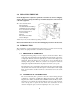
• Flooded suction mounting (installing the pump at the base of the chemical storage tank, Figure 4) is the most trouble free type of installation and is recommended for very low output requirements. Since the suction tubing is filled with chemical, priming is accomplished quickly and the chance of losing prime is reduced. To mount pump, drill four holes of .25” (6 mm) diameter in the shelf as shown in the dimension drawing (Figure 2). Attach pump securely using four #10 (M5) bolts and nuts.
4.2 PIPING • Use provided tubing of specified size for connection. Connect tubing securely to prevent leakage of chemical and the entrance of air. Since plastic nuts are used for fittings, they should not be tightened excessively (i.e. hand tighten only). NPT suction and discharge valves must NOT be over tightened. Hold fitting in place while adding piping and fittings. NPT suction and discharge valves should only be tightened 25 to 35 in. lbs. (4.5-6.3 kg/cm).
4.3 WIRING 4.4 • —Risk of electrical shock. This pump is supplied with a three-prong grounding type power plug. To reduce risk of electric shock, connect only to a properly grounded, grounding type receptacle. • The metering pump should be wired to an electrical source, which conforms to those on the pump data label. Applying higher voltage than the pump is rated for will damage the internal circuit.
FIGURE 8 5.0 START UP AND OPERATION 5.1 POWER All metering pumps are available in 115 and 230 volts at 50/60 Hertz, single phase. In addition, certain models are available in 12 volt DC. Prior to start-up always check to insure that the pump voltage/frequency/phase matches that of the power supply. If pump is fitted with a PVC pump head (7th position of model number is “V” or "W". Note: PVC is gray, not black), uniformly hand tighten the four head screws before use, 18-22 in. lbs. (3.2 -3.9 kg/cm).
• Turn on the power to the pump. The green LED (not available on all models) will light up and flash off each time the pump strokes. • Adjust the stroke rate knob to the 100% setting mark (for more information see Section 5.3, Capacity Control). • Adjust the stroke length knob to the 100% setting mark if applicable (for more information see Section 5.3, Capacity Controls).
5.3 CAPACITY CONTROL Capacity can be controlled by means of the stroke length adjusting knob and/or stroke rate adjusting knob (except model C pumps). Control knobs provide coarse adjustment; use a calibration column for accurate calibration. Contact your pump supplier for proper calibration equipment. 5.3.1 Stroke Frequency Adjustment (E, E-DC, E Plus, A Plus & C Plus only) • Stroke frequency can be controlled from 10 to 100% (12 to 125 strokes per minute) by means of the electronic circuit.
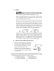
5.3.3 Controlling Procedure cont'd. Example Selected Model Set Stroke Length Set Stroke Rate Output Capacity (Rated Pressure) = = = = LPD4 100% 100% 21 gallons per day (GPD)* Desired Flow = Adjust Stroke Rate to 80% Output Capacity = 15 GPD Stroke Length Setting 15 x 100 = 90% approximate 16.8 = 0.80 x 21 = 16.8 GPD* Thus to obtain the desired flow, stroke length is set at 90% and stroke rate is set at 80% i.e. output capacity = 0.90 x 0.80 x 21 = 15.
5.5 OPERATION BY EXTERNAL INPUT SIGNALS (Options): The pump can be controlled by three types of input signals. All are fully isolated from AC input and from earth ground. The input socket connections are located at the bottom of the control panel face and the signal cords are provided with the pump. Remove rubber plugs to access plug sockets. 5.5.1 STOP FUNCTION (E Plus, A Plus, C Plus & C only) Operation of the pump can be stopped by an external signal input.
• When the “ON” signal pulse is input, the pump operates one stroke and the fluid is discharged. In addition, the pump can be operated continuously at a rate of up to 125 strokes/min. by repeated input of “ON” and “OFF” signals. • After receiving an input signal, the pump generates the necessary power pulse to actuate the solenoid. The external signal input is debounced by the pump circuit.
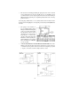
5.5.3 4-20mA DC INPUT FUNCTION cont'd. • The signal cord polarity is: Black = Common White = Positive Wrong polarity can result in excess flow. Signal input impedance is 124 ohms. Remove cap from pump socket labeled 4-20 mA, use polarized cord supplied with pump to connect control circuit to pump. Plug cord into pump socket labeled 4-20 mA. 6.
• If the pump has been out of service for a month or longer, clear the pump head valve assemblies by pumping fresh water for approximately 30 minutes. If the pump does not operate normally after this “purging run”, replace cartridge valve assemblies. 6.2 DISASSEMBLY AND ASSEMBLY DIAPHRAGM REMOVAL Flush pump head and valve assemblies out by running pump with water or other suitable neutralizing solution. Wash outside of pump if chemical has dripped on pump.
6.3 DIAPHRAGM REPLACEMENT cont'd. • Apply grease to areas of the diaphragm that contact the deflection plate. • Slide the diaphragm deflection plate onto the back of the diaphragm stud, radius side towards the diaphragm. Next slide two shims onto the diaphragm threaded stud and screw the diaphragm into the EPM unit. Refer to Figure 14. Turn diaphragm clockwise until deflection plate and shims are tight against solenoid shaft and the diaphragm stops turning.
7.0 TROUBLESHOOTING PROBABLE CAUSE PROBLEM REM EDY 1. Leak in suction side of pump. 1. Examine suction tubing. If worn at the end , cut approximately one inch (2.5 cm) off and reconnect. 2. Valve seats not sealing. 2. Clean valve seats if dirty or replace with alternate material if deterioration is noted. 3. Low setting on pump. 3. When pumping against pressure, the dial should be set above 20% capacity for a reliable feed rate. 4. Low suction level. 4.
7.0 TROUBLESHOOTING cont'd. PROBABLE CAUSE PROBLEM LOSS OF CHEM ICAL RESIDUAL REM EDY 1. Pump setting too low. 1. 2. Scale at injection point. 2. 3. Solution container allowed to run dry 3. 1. Pump setting too high. 1. Lower pump setting (pump must be operting to adjust stroke length knob). 2. Chemical in solution tank too rich. 2. Dilute chemical solution.
7.0 TROUBLESHOOTING cont'd. PROBLEM PROBABLE CAUSE REM EDY 1. Dirty check valve. 1. Remove and replace or clean off any scale or sediment. 2. Ball checks not seating or not sealing properly. 2. Check seat and ball checks for chips, clean gently. If deformity or deterioration is noted, replace part with proper material. Resulting crystals can hold check valves open, therefore, the valves must be disassembled and cleaned. 3. Solution container allowed to run dry. 3.
8.0 POLICIES AND PROCEDURES 8.1 MANUFACTURERS PRODUCT WARRANTY The manufacturer warrants its equipment of its manufacture to be free of defects in material or workmanship Liability under this policy extends for eighteen (18) months from the date of purchase or one (1) year from date of installation or whichever comes first. The manufacturer’s liability is limited to repair or replacement of any device or part, which is returned, prepaid, to the factory and which is proven defective upon examination.
8.3 RETURNS The Customer Service Department will issue a Return Authorization (RA) number for all returns. The following information will be required: 1. 2. 3. 4. 5. 6. Billing and a ship-to address. Model and serial number. Contact name and phone number. Reason for return. Purchase order (where applicable). RA number on outside of the carton. All material must be returned freight prepaid. All merchandise must be properly packaged and free of any corrosive, toxic or otherwise hazardous chemical.