INSTALLATION OPERATION AND MAINTENANCE MANUAL MODELS DLR-A WEDECO DLR A SERIES ULTRAVIOLET WATER DISINFECTION UNIT SERIES NO'S 1 2 4 Sold by: Manufactured by: WEDECO Ideal Horizons, Inc. CAUTION 3520 Westinghouse Blvd. Charlotte, NC 28273 TEL: (704) 716-7600 FAX: (704) 716-7601 www.wedecouv.com IT IS VERY IMPORTANT THAT THOSE RESPONSIBLE FOR THE INSTALLATION OF THIS EQUIPMENT, AS WELL AS THE OWNER/OPERATOR, READ THIS MANUAL AND CAREFULLY FOLLOW THE INSTRUCTIONS AND GUIDELINES.
Table of Contents Important Safety Instructions...................................................................................................................... 3 Pre-Installation Instructions ..................................................................................................................... 4-6 Installing the Disinfection Unit................................................................................................................... 8 Mounting Electrical Control Box..........
Important Safety Instructions To guard against injury, basic safety precautions must be observed. WARNING! READ AND FOLLOW ALL SAFETY INSTRUCTIONS AND SAFE THESE INSTRUCTIONS CAUTION! Denotes a potentially dangerous situation. Failure to observe this warning may lead to minor or serious personal injury and material damage. ELECTRIC SHOCK! Warning — Dangerous electric voltage. Failure to observe this warning may lead to serious injury or death.
Pre-Installation Instructions IMPORTANT Please read before installing your Ultraviolet System When this unit is wired in conjunction with another electrical devise you may experience a drop in voltage. It is recommended that your Ultraviolet System NOT share a circuit with another electrical device. The maximum voltage threshold for this system is 130V. The minimum voltage threshold for this system is 105V. Please ensure that proper voltage requirements are meet before installing your Ultraviolet System.
5 Select a location that meets the following guidelines. x The unit must be installed between the cold water source and the water heater as inlet temperature must not exceed 100oF. (See Figure 1 for proper installation sequence.) x The disinfection unit can be installed either horizontally or vertically. (See Figure 3 for water flow direction.) x There must be enough clearance to remove the UV lamp and the quartz sleeve for replacement and regular maintenance.
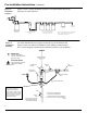
Pre-Installation Instructions, Continued Figure 1: Installation Sequence Figure 1 shows a typical installation sequence. Note that all items may not be necessary for water treatment.
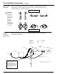
Pre-Installation Instructions, Continued Figure 3: Unit Positioning Figure 3 shows proper water flow for horizontal or vertical installation. Make certain that your unit and the inlet and outlet pipes are in the right position for either horizontal or vertical installation. Correct Installation IMPORTANT! For vertical installation, the inlet is at the bottom and the outlet is near the top of the disinfection chamber. For horizontal installation pay careful attention to the diagram for flow direction.
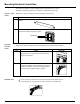
Installing the Disinfection Unit Attaching unit to wall 8 Follow these steps to attach WEDECO UV disinfection chamber to the wall. Step Action 1 Install the two wall mount brackets on the wall using the proper screws for your wall type (screws not included). 2 Place disinfection chamber in the brackets and secure with the wall mount bracket straps. Use the wall mount bracket strap screws provided to tighten the wall mount bracket straps to the wall mount brackets.
Mounting Electrical Control Box The electrical control box can be mounted on the wall (Option A) or on the disinfection chamber (Option B), according to the following instructions. Option A: Wall mount Follow these steps to mount the electrical control box on the wall. Step Action 1 Attach the optional wall mount bracket to the wall using suitable hardware for your wall surface.
Installing the UV Lamp CAUTION UV lamp is very fragile. Do not handle it with bare hands. Use clean cotton gloves or cloth when handling lamp to keep it free of dust or fingerprints. If dust or fingerprints get on the lamp, wipe it with a clean cloth and alcohol. Insert lamp in chamber Follow these steps to install the UV lamp in the disinfection chamber. Step 1 Action Insert the lamp into the headpiece.
Installing the UV Lamp, Continued Position GloCap The Glo-Cap must be properly placed on the headpiece for the UV disinfection unit to work. Follow the steps below to position the Glo-Cap. Step 1 2 Action Align the tab on the Glo-Cap with the middle tab on the transparent clip. Lower the Glo-Cap onto the headpiece until it clicks into place. If it does not click into place, make sure that the tabs on the Glo-Cap are not over the raised tabs on the headpiece. If they are, turn the Glo-Cap.
Pre-Start Up Sequence Follow these steps before operating your WEDECO disinfection unit. Before using the unit… Step 1 2 Action Check your plumbing: x Make sure that new plumbing has no leaks. x Flush pipes to purge soldering residue or other debris from the system. x Expel air from the system to avoid pressure damage to the unit. Before initial use of your UV system and after routine maintenance procedures, you should sanitize your water system to ensure that no organisms are present.
Start-Up Sequence Before using the unit… Follow the start-up procedures below. If your unit is… DLR A Then… x x x x x Slowly fill the unit with water. Plug power cord into wall outlet. Wait 30 seconds. If the lamp is working, the "Power On" LED will light. Turn off water flow. Sanitize your system before using your household water (see maintenance section for instructions. Slowly fill the unit with water.
Maintenance Required maintenance Periodically, you will need to perform routine maintenance procedures on your WEDECO UV disinfection unit. This section provides directions for: x Replacing the lamp (every 365 days or in the event of a lamp-out alarm). x Cleaning the quartz sleeve (as needed). x Replacing the headpiece O-ring (every 365 days or when needed, based on visual inspection). Replacing the lamp The UV lamp is rated to provide 365 days of continuous use.
Maintenance, Continued The quartz sleeve must be kept clean to kill bacteria effectively. Your water quality and mineral content will determine cleaning frequency. Perform a visual inspection after thirty (30) days of operation. If the sleeve is dirty, shorten cleaning intervals. If the sleeve is clean, lengthen cleaning intervals. At this time, clean the headpiece and O-Ring also. Cleaning the quartz sleeve, headpiece, & O-Ring Step Action 1 2 3 Fill bucket or other receptacle with warm, soapy water.
Maintenance, Continued Replacing the O-Ring General maintenance for the O-Ring requires that you replace it every 365 days. If, however, during routine cleaning of the quartz sleeve, you find the O-Ring cut, damaged, or extremely dirty, then it should be replaced at this time. To replace the O-Ring, follow the directions for cleaning.
Maintenance Log Note You must perform routine maintenance in order to achieve optimum performance levels from your WEDECO UV disinfection unit. As you perform routine maintenance or necessary service on your unit, record the dates in the maintenance log. The maintenance section of the Owner’s Manual provides instructions for servicing and maintenance procedures.
Parts List KEY # PART # QTY.
Alarms The front panel of the electrical control box has the following LED displays: Displays LED Displays Diagram x POWER ON: green x LAMP OUT: red LAMP ON STATUS REPLACE LAMP ALARM The WEDECO UV disinfection unit has built in alarms to warn of inefficient performance or lamp failure. Alarm activation Model DLR-A What Happens . x x The LAMP OUT LED is illuminated continuously. The internal ALARM buzzer beeps continuously. Cause How to Resolve Ɣ Lamp has failed due to another problem.
Troubleshooting Determining problem The troubleshooting guide gives you suggestions for resolving problems. If… Then… The unit is leaking water x x x x x x Glo-Cap is not lit or has gone out x x x Poor bacterial performance x x x x Power fails Display screen is blank Unit gives faulty alarms 20 x Ensure that the headpiece is tight. Verify that inlet water pressure is not >125 psi. Ensure that headpiece O-ring is seated properly. Lubricate O-ring (use food-grade silicone).
Technical Specifications: DLR Series All prices and specifications are subject to change without notice. Technical Description Description UV disinfection chamber UV lamp Control Box Application Operational capacity Options The DLR Series is designed with a single low-pressure high-intensity UV lamp centered inside a protective quartz sleeve. The disinfection chamber is either 304 or 316L stainless steel and is electro-polished with male NPT Inlet/Outlet.
Technical Specifications: DLR Series, Continued Control Box DLR type Width (inches) approx. Height (inches) approx. Depth (inches) approx. Weight (lb) approx. Voltage (V/Hz) Cable length chamber/cabinet (ft) Ambient temperature (ºF) Power consumption (W) 1 6.61 7.87 2.6 5.51 120V/60Hz 4.9 95 35 2 6.61 7.87 2.6 5.51 120V/60Hz 4.9 95 55 4 6.61 7.87 2.6 5.51 120V/60Hz 4.9 95 55 The DLR-AP is available in different sizes based on flow capacity.
Warranty Note Save sales slip or cancelled check for proof of original purchase date to establish warranty period. FULL ONE-YEAR WARRANTY ON UV DISINFECTION UNIT: For one (1) year from date of purchase, when this UV water disinfection unit is installed and maintained in accordance with our instructions, WEDECO will repair, free of charge, defects in material or workmanship in this UV water disinfection unit.