
Manual


Pre-Installation Instructions, Continued
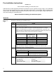
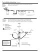
Figure 3: Unit
Positioning
Figure 3 shows proper water flow for horizontal or vertical installation. Make
certain that your unit and the inlet and outlet pipes are in the right position for
either horizontal or vertical installation.
INLET
OUTLET
FLOW
DIRECTION
OUTLET
INLET
DIRECTION
FLOW
INLET
OUTLET
INLET
OUTLET
FLOW
DIRECTION DIRECTION
FLOW
OUTLET OUTLET
INLET INLET
DIRECTION
FLOW
DIRECTION
FLOW
FLOW
DIRECTION
FLOW
DIRECTION
INLET
OUTLET
INLET
OUTLET
Correct Installation
IMPORTANT!
For vertical
installation, the
inlet is at the
bottom and the
outlet is near the
top of the
disinfection
chamber. For
horizontal
installation pay
careful attention to
the diagram for
flow direction.
Incorrect Installation
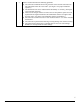
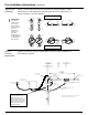
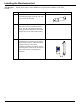
Figure 4:
Clearance
Requirements
Figure 4 provides the clearance requirements needed for proper installation of
the disinfection chamber.
IN L E T
OUTLET
FLOW
DIRECTION
ELECTRICAL
CONTROL BOX
MINIMUM CLEARANCE
IS L E N G T H O F U N IT
PLUS 4"
MINIMUM
20.00"
FLOW RESTRICTOR
LOCATION
FLOW
RESTRICTOR
UNIT
DLR 1
DLR 2
DLR 4
DLR 7 44.6"
30.4"
30.4"
22.5"
MIN. CLEARANCE
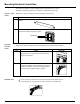
ELECTRICAL
OUTLET
POWER CORD
(7' 5" LO N G )
SOLENOID POW ER CORD
(8' LON G )
SENSOR CORD
(42" LO N G )
WEDECO
U V DIS IN FEC TIO N
CHAMBER
LAM P CORD
(42" LONG)
*
*
IN S T A LL F LO W R E S T R IC T O R W ITH A R R O W
IN DIRECTION OF WATER FLOW.
OPTIONAL SOLENOID
VALVE
SENSOR
(DLR-M O NLY)
The disinfection chamber must
be properly grounded to a
suitable electrical ground.
Check local electrical codes for
p
roper location. Attach ground
wire (not included) to stud and
nut located on lower area of
disinfection chamber.
7