
Instructions / Assembly


II
GENERAL INFORMATION
1240 SERIES MODELS AND SYSTEM CONFIGURATIONS Table 1
Item #
Model
Description
Number
of
Vessels
Vessel 1 Vessel 2 Vessel 3 Vessel 4
Output
(2)
(GPD)
Monitor
(4)
Model Series 12401
1240101-##
(1)
3VTFC25G 3 N/A
Dual
Purpose
TFC
(3)
Membrane
Carbon Filter 25
1240102-##
(1)
3VTFC50G 3 N/A
Dual
Purpose
TFC
(3)
Membrane
Carbon Filter 50
None
Model Series 12402
1240200-##
(1)
4VTFC09G 4
Sediment
Filter
Carbon Filter
TFC
(3)
Membrane
Carbon Filter 9
1240201-##
(1)
4VTFC25G 4
Sediment
Filter
Carbon Filter
TFC
(3)
Membrane
Carbon Filter 25
1240202-##
(1)
4VTFC50G 4
Sediment
Filter
Carbon Filter
TFC
(3)
Membrane
Carbon Filter 50
1240203-##
(1)
4VTFC75G 4
Sediment
Filter
Carbon Filter
TFC
(3)
Membrane
Carbon Filter 75
None
Model Series 12403
1240300-##
(1)
4VTFC09G-PB 4
Sediment
Filter
Carbon Filter
TFC
(3)
Membrane
Carbon Filter 9
1240301-##
(1)
4VTFC25G-PB 4
Sediment
Filter
Carbon Filter
TFC
(3)
Membrane
Carbon Filter 25
1240302-##
(1)
4VTFC50G-PB 4
Sediment
Filter
Carbon Filter
TFC
(3)
Membrane
Carbon Filter 50
1240303-##
(1)
4VTFC75G-PB 4
Sediment
Filter
Carbon Filter
TFC
(3)
Membrane
Carbon Filter 75
Smartap
®
Push
Button
CONDITIONS FOR USE Table 2
Source Water Supply Profile Chemical Parameters Max mg/L
Community/Private Chlorinated/Non-Chlorinated Hardness (CaCO
3
) <350 (20 gpg)
Feed Water Pressure
(5)
242-690 kPa (35-100 psig) Iron (Fe ) <0.1
Temperature 4°-38° C (40°-100° F) Manganese (Mn) <0.05
pH Range 3.0 - 11.0 Hydrogen Sulfide (H
2
S ) 0.00
Maximum TDS Level 2000 mg/L Residual Chlorine (Cl
2
) <2.0
Turbidity** <1.0 NTU
Maximum SDI***
<4.0
** Nephelometric Turbidity Unit
*** Silt Density Index: Value stated in SDI units.
NOTES:
1. ## is an item number suffix which refers to various product appearances or optional components supplied with the model.
2. Manufacturer’s Specification only with inlet conditions of 345 kPa (50 psig), 25° C (77° F), going to atmosphere.
3. TFC refers to reverse osmosis membranes constructed from a THIN FILM COMPOSITE.
4. SMARTAP
®
PUSH BUTTON MONITOR: Indicator lights located on the module cover report system status.
5. PRESSURE REGULATOR IS RECOMMENDED FOR FEED WATER PRESSURES EXCEEDING 552 kPa (80 psig).
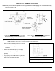
OPTIONS AND ACCESSORIES
PRODUCT WATER FAUCETS BOOSTER PUMP
Faucets may be supplied as Air Gap or Non-Air Gap.
A booster pump may be used if system pressure is below 242 kPa (35 psi).
Pump should be placed near RO Module and installed in feed water line just
before it enters Module.