
Instructions / Assembly


3
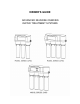
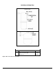
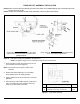
SADDLE-TAPPING VALVE INSTALLATION ON COPPER TUBE
CAUTION: This saddle-tapping valve is not designed for installation on flex line tubing.
NOTE: State, provincial and local plumbing codes may prohibit use of saddle-tapping valves.
1. CAUTION: If no shut off valve is installed under
sink, close main water valve during this Installation.
Locate shut off valves on water lines under sink. To
identify hot supply pipe and cold supply pipe, turn
both faucets on and let water run. As water flows, hot
water pipe becomes noticeably warmer.
2. CAUTION: Do not install feed water assembly on hot
water line.
Turn off cold water supply by closing shut off valve.
Drain line by opening sink faucet. Some mixing type
faucets may require hot water supply be shut off as
well.
NOTE: All instructions refer to components shown in
Figure 3 unless otherwise noted.
3. CAUTION: Do not turn valve handle before or while
installing saddle-tapping valve. Make sure piercing
lance does not protrude beyond rubber gasket before
installing valve.
Assemble saddle-tapping valve assembly on tube.
a. Hold back plate against tube.
• 3/8" copper tubing use back plate smaller
radius.
• 1/2" copper tubing, use back plate larger
radius
b. Hold valve saddle against tubing in a position
directly opposite back plate.
c. Tighten screw enough so valve saddle and back
plate are held securely against tube.
d. Rotate assembly so tubing connection is aligned
toward RO Module feed port.
e. Tighten screw firmly. Do not crush tube.
4. Connect source water feed tubing to valve body
using compression fitting.
a. Slide nut and sleeve onto tubing (in that order).
b. Install insert into plastic tubing.
c. Install tube with insert and sleeve into valve body.
d. Thread compression nut onto valve body, tighten.
5. Turn saddle-tapping valve handle clockwise until it is
firmly seated and piercing lance is fully extended.
6. CAUTION: Supply line is pierced and valve is closed.
Do not open valve until system is activated (Page 10).
Turn on cold water supply. Check saddle-tapping
valve installation for leaks. Allow water to run from
faucet for a few minutes to clear any debris in the line
caused by installation.
NOTE: If flow from sink faucet is reduced, clean
faucet aerator.
EXISTING 1/2"
COPPER TUBING
HOUSEHOLD
COLD WATER LINE
REVERSIBLE
BACK PLATE
COMPRESSION
NUT
TUBING TO MODULE
(1/4" WHITE TUBING
SLEEVE
INSERT
VALVE HANDLE
TIGHTENING
SCREW
STEM SEAL NUT
VALVE SADDLE
SMALLER RADIUS
LARGER RADIUS
VALVE BODY
Figure 3: Saddle-Tapping Valve Assembly
P/N 92276 installed on
1/2” Copper Tubing
7. Trim ¼” white tube to desired length. Install ¼” white
tube into ¼” white collet as shown in Figure 1.A.
ADDITIONAL POINT OF USE CONNECTION
NOTE: Icemakers typically use 1/4" tubing as feed line. Use a reducing union (P/N 92402) for this connection.
NOTE: Reduce the 3/8” Line to 1/4” as close as possible to the additional point-of use device to minimize flow loss.
1. To connect an additional point of use (icemaker, extra
faucet in wet bar and/or another use for treated water),
place a "tee" connector (P/N 92403) in 3/8" blue line
between faucet and RO Module.
2. Connect "tee" to point-of-use with 3/8" blue tubing
(P/N 87600). Connect tubing to point-of-use.
Connector requirements are based on type of
delivery device i.e., a typical icemaker uses
3/8" x 1/4" reducing device.